
DC Motor 11 click


Prices incl. GST
Out of Stock.
- Product Code: MIKROE-3649
- MPN: 3649
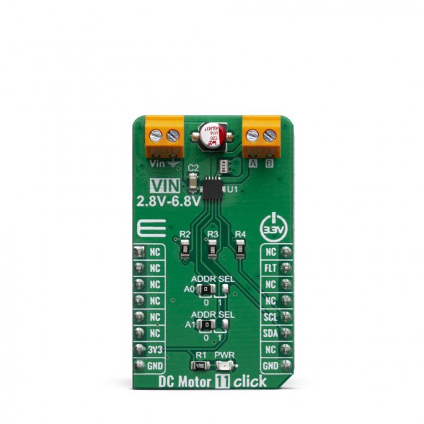
DC Motor 11 Click is a brushed DC motor driver with the current limiting and current sensing. It is based on the DRV8830, an integrated H-Bridge driver IC, optimized for motor driving applications. It can be operated by two logic signals, allowing to drive the connected motor in two different ways: it can use fixed logic levels for the direction control, or it can be controlled by a PWM signal, offering an additional speed control option. The DRV8830 also contains a set of protection features, offering a very high level of reliability. Besides driving capabilities, DC Motor 11 click can also sense current consumption at its output.
DC Motor 11 click is supported by a mikroSDK compliant library, which includes functions that simplify software development. This Click board™ comes as a fully tested product, ready to be used on a system equipped with the mikroBUS™ socket.
This Click board™ is optimized for driving brushed DC motors. it integrates an efficient H-Bridge with very low ON resistance of approximately 500mΩ through each branch. An integrated sleep mode is activated when both logic inputs are at a LOW logic level for longer than 1ms, reducing the overall power consumption. A dedicated, high-precision current sensing amplifier IC is used to sense the current through motor coils, allowing the host MCU to perform current monitoring at all times. DC Motor 11 click is perfectly suited for rapid development of various DC motor driving applications, including home appliances, printers, industrial equipment, mechatronic applications, etc.
HOW DOES IT WORK?
DC Motor 11 click is designed around the DRV8830, a Low-Voltage Motor Driver With Serial Interface, by Texas Instruments. This IC is actually an integrated H-Bridge driver with the current regulation circuit that allows limiting the current through the connected load, with just a single resistor. A very low ON resistance through the H-Bridge reduces the overall power dissipation, while an advanced control circuit injects dead-time intervals, whenever the outputs change their state, preventing current shoot-throughs. The DRV8830 integrates a set of protection features, including undervoltage, overcurrent, and overtemperature protection. Each of these events will cause the H-Bridge MOSFETs to be disabled. After a fault condition has been removed, the device will continue its operation.
The DRV8830 includes an internal reference voltage that is connected to a DAC. This DAC generates a voltage which is used to set the PWM regulated output voltage, and therefore speed and direction of the motor rotation. The DAC is controlled by the VSET bits from the I2C interface. For the detailed commands for desired output voltages, refer to DRV8830 datasheet.
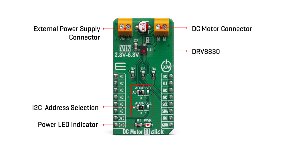
DC Motor 11 click uses I2C interface to communicate with the main MCU, as well as fault pin (FLT), which is routed to the INT pin of the mikroBUS™ socket. I2C address can be selected using an additional SMD jumpers (JP1 and JP2), labeled as ADDR SEL, determining the least significant bits of the DRV8830 slave I2C address.
Although the DRV8830 supports up to 1A Maximum DC/RMS or Peak Drive Current Current through the connected load, it is limited to maximum 0.6A. Higher current will cause the overcurrent protection to be activated. Peak current through the motor is limited to about 1A, ensuring reliable spin-up while preventing the overcurrent protection to be activated, even if a large load torque is applied. Although there is a very low resistance across the H-Bridge, the current should be monitored to prevent excessive heating in situations where the load is reasonably high.
The Click board™ can operate with 3.3V MCUs only, it is set to work over the I2C by default, and it is already equipped with the pull-up resistors. It is ready to be used as soon as it is inserted into a mikroBUS™ socket of the development system.
SPECIFICATIONS
| Type | Brushed |
| Applications | DC Motor 11click is perfectly suited for rapid development of various DC motor driving applications, including home appliances, printers, industrial equipment, mechatronic applications, etc. |
| On-board modules | DRV8830, Low-Voltage Motor Driver With Serial Interface |
| Key Features | The main IC features a set of protection features, allowing for reliable performance. It allows the motor current to be monitored at all times. It also features high efficiency, it can be operated within a wide voltage range. |
| Interface | Analog,GPIO |
| Click board size | M (42.9 x 25.4 mm) |
| Input Voltage | 5V |
PINOUT DIAGRAM
This table shows how the pinout on DC Motor 11 click corresponds to the pinout on the mikroBUS™ socket (the latter shown in the two middle columns).
| Notes | Pin | Pin | Notes | ||||
|---|---|---|---|---|---|---|---|
| NC | 1 | AN | PWM | 16 | NC | ||
| NC | 2 | RST | INT | 15 | FLT | Fault Output | |
| NC | 3 | CS | RX | 14 | NC | ||
| NC | 4 | SCK | TX | 13 | NC | ||
| NC | 5 | MISO | SCL | 12 | SCL | I2C Clock | |
| NC | 6 | MOSI | SDA | 11 | SDA | I2C Data | |
| Power supply | 3V | 7 | 3.3V | 5V | 10 | NC | |
| Ground | GND | 8 | GND | GND | 9 | GND | Ground |
ONBOARD SETTINGS AND INDICATORS
| Label | Name | Default | Description |
|---|---|---|---|
| LD1 | PWR | - | Power LED Indicator |
| TB1 | POWER | - | External PSU connector |
| TB2 | MOTOR | - | DC Motor connector |
| JP1,JP2 | ADDR SEL | Left | I2C address LSB selection: left position 0, right position 1 |
DC MOTOR 11 CLICK ELECTRICAL SPECIFICATIONS
| Description | Min | Typ | Max | Unit |
|---|---|---|---|---|
| Input voltage | 2.75 | 6.8 | V | |
| Current through the load | 0 | 1 | A |
SOFTWARE SUPPORT
We provide a library for the DCMotor11 click on our LibStock page, as well as a demo application (example), developed using MikroElektronika compilers. The demo can run on all the main MikroElektronika development boards.
Library Description
The library contains all the necessary functions for full DC motor control.
Key functions:
void dcmotor11_control(uint8_t dir, uint8_t speed)- Motor Control.void dcmotor11_stop()- Motor Stop.uint8_t dcmotor11_getFault()- Get Fault.
Examples description
The application is composed of three sections :
- System Initialization - Initialzes I2C module and sets INT pin as INPUT
- Application Initialization - Initialization driver init and sets first motor settings.
- Application Task - Waits for valid user input and executes functions based on set of valid commands.
- Commands : '+' - Voltage (Speed) up '-' - Voltage (Speed) down 's' - Motor State - Stop/Start 'd' - Direction - Forword/Backword
void applicationTask()
{
uint8_t dataReady_;
char receivedData_;
dataReady_ = UART_Rdy_Ptr( );
if (dataReady_ != 0)
{
receivedData_ = UART_Rd_Ptr( );
switch (receivedData_)
{
case '+' :
{
/* Speed increase */
motorSpeed += 4;
if(motorSpeed >= _DCMOTOR11_VSET_4820mV)
{
mikrobus_logWrite("---- MAX SPEED ----", _LOG_LINE);
motorSpeed = _DCMOTOR11_VSET_4820mV;
dcmotor11_control(motorDir, motorSpeed);
}
else
{
mikrobus_logWrite("---- Speed increase ----", _LOG_TEXT);
mikrobus_logWrite(" MOTOR SPEED: ", _LOG_TEXT);
IntToStr(motorSpeed, demoText);
mikrobus_logWrite(demoText, _LOG_LINE);
dcmotor11_control(motorDir, motorSpeed);
}
break;
}
case '-' :
{
/* Speed decrease */
motorSpeed -= 4;
if( motorSpeed < _DCMOTOR11_VSET_480mV )
{
mikrobus_logWrite("---- MIN SPEED ----", _LOG_LINE);
motorSpeed = _DCMOTOR11_VSET_480mV;
}
else
{
mikrobus_logWrite("---- Speed decrease ----", _LOG_TEXT);
mikrobus_logWrite(" MOTOR SPEED: ", _LOG_TEXT);
IntToStr(motorSpeed, demoText);
mikrobus_logWrite(demoText, _LOG_LINE);
dcmotor11_control(motorDir, motorSpeed);
}
break;
}
case 's' :
{
/* Stop / Start */
if(fMotorState == 1)
{
mikrobus_logWrite("---- Stop Motor!!! ----", _LOG_LINE);
fMotorState = 0;
dcmotor11_stop();
}
else
{
mikrobus_logWrite("---- Start Motor ----", _LOG_LINE);
fMotorState = 1;
motorSpeed = _DCMOTOR11_VSET_480mV;
dcmotor11_control(motorDir, motorSpeed);
}
break;
}
case 'd' :
{
/* Direction - Forward / Backword */
if(motorDir == 2)
{
mikrobus_logWrite("---- Direction - [FORWARD] ----", _LOG_LINE);
motorDir = 1;
dcmotor11_control(motorDir, motorSpeed);
}
else
{
mikrobus_logWrite("---- Direction - [BACKWARD] ----", _LOG_LINE);
motorDir = 2;
dcmotor11_control(motorDir, motorSpeed);
}
break;
}
}
}
}
The full application code, and ready to use projects can be found on our LibStock page.
Other mikroE Libraries used in the example:
- I2C
- UART
- Conversions
Additional notes and informations
Depending on the development board you are using, you may need USB UART click, USB UART 2 click or RS232 click to connect to your PC, for development systems with no UART to USB interface available on the board. The terminal available in all MikroElektronika compilers, or any other terminal application of your choice, can be used to read the message.
MIKROSDK
This Click board™ is supported with mikroSDK - MikroElektronika Software Development Kit. To ensure proper operation of mikroSDK compliant Click board™ demo applications, mikroSDK should be downloaded from the LibStock and installed for the compiler you are using.
For more information about mikroSDK, visit the official page.