
H-bridge 3 click


Prices incl. GST
Out of Stock.
- Product Code: MIKROE-3613
- MPN: 3613
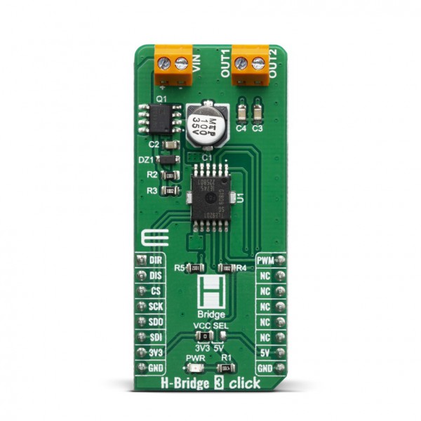
H-Bridge 3 Click is designed for the control of small DC motors and inductive loads, it features TLE9201SG a general purpose 6A H-Bridge perfectly suited for industrial and automotive applications. This IC meets the harsh automotive environmental conditions and it is qualified in accordance with the AEC-Q100 standard, also has set of features such as the short circuit and over-temperature protection, under-voltage protection, detailed SPI diagnosis or simple error flag and fully 3.3/5.5V compatible logic inputs.
H-bridge 3 click is supported by a mikroSDK compliant library, which includes functions that simplify software development. This Click board™ comes as a fully tested product, ready to be used on a system equipped with the mikroBUS™ socket.
H-Bridge 3 click can be used to drive a H-Bridge motor by changing output states. The outputs can be pulse width modulated at frequencies up to 20kHz by means of PWM/DIR control. While the signal at the direction input defines the direction of the DC motor, the PWM signal controls the duty cycle. PWM/DIR control reduces the number of PWM capable pins needed at the microcontroller.
For load currents above the current limitation threshold (7A typ.) the H-Bridge switches into chopper current limitation mode. The H-bridge 3 click is protected against short circuits and over temperature and provides diagnosis via SPI or basic error feedback via status flag. Open load can be detected when the bridge is disabled or during PWM operation of inductive loads.
HOW DOES IT WORK?
The main component used on the H-Bridge 3 click is the TLE9201SG, an H-Bridge DC motor driver, with up to 28V and 6A, from Infineon. This IC is an efficient integrated H-bridge driver, with very low RDS ON output per switch. H-bridge in general, allows the current to flow in one or another direction.
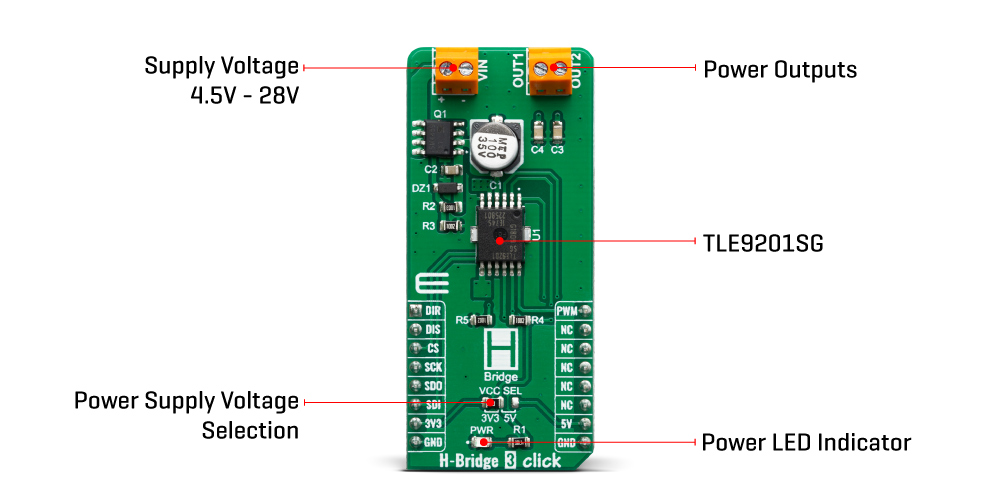
All internal supply voltages are derived from the external VIN conector. A charge pump provides the gate voltage for the high side switches. The output buffer of the digital output SO is supplied by the pin VSO. Therefore the output logic level at SO can be easily configured for 3.3 V or 5 V logic by moving VCC SEL jumper to the respective voltage.
The output stages consist of four n-channel mosfets in H-bridge configuration. The outputs are protected against short circuits and over temperature. The bridge is controlled using the inputs PWM and DIR. The signal at DIR is defining the direction of the driven DC motor whereas the PWM signal sets the duty cycle. The outputs can be set tristate (i.e. high side and low side switches are turned off) by setting DIS to high level.
For diagnosis purposes the TLE9201SG is equipped with a “Serial Peripheral Interface“ (SPI). The H-bridge 3 click is configured as a “slave” device. This means that the host microcontroller as the master is providing the chip select (CS) and clock signal (SCK).
A data transfer on the SPI bus is initiated with a falling edge on CS and is terminated by a rising edge on CS. The data on the serial input pin SI is sampled with the falling edge of SCK, the serial data output at MISO is determined by the rising clock edge. The data is transferred “MSB first”. The word length of the SPI is 8 bit. Please note that there is no check for the number of clocks within a SPI frame. Any low pulse at CS line will be regarded as one frame.
The H-Bridge 3 click comes with a mikroC, mikroBASIC, and mikroPASCAL compilers compatible library, which contains functions for easy and simple operating of this Click board™. The provided example application demonstrates their usage and can be used as a reference for custom projects.
SPECIFICATIONS
| Type | Brushed |
| Applications | This click board can be used for exhaust gas recirculation (ERG), idle speed control, auxiliary water pump or any industrial DC applications |
| On-board modules | TLE9201SG is a general purpose 6 A H-Bridge, designed for (but not limited to) the control of DC motors or other inductive loads in automotive applications. |
| Key Features | TLE9201SG are equipped with fault diagnostic functions as: short to battery voltage (SCB), short to ground (SCG), open load (OL), over-temperature (OT) |
| Interface | GPIO,SPI |
| Click board size | L (57.15 x 25.4 mm) |
| Input Voltage | 3.3V or 5V |
PINOUT DIAGRAM
This table shows how the pinout on H-Bridge click corresponds to the pinout on the mikroBUS™ socket (the latter shown in the two middle columns).
| Notes | Pin | Pin | Notes | ||||
|---|---|---|---|---|---|---|---|
| Direction Input | DIR | 1 | AN | PWM | 16 | PWM | Speed control |
| Output Disable | DIS | 2 | RST | INT | 15 | NC | |
| Chip Select | CS | 3 | CS | RX | 14 | NC | |
| Serial Clock | SCK | 4 | SCK | TX | 13 | NC | |
| Serial Data Output | SDO | 5 | MISO | SCL | 12 | NC | |
| Serial Data Input | SDI | 6 | MOSI | SDA | 11 | NC | |
| Power Supply | 3.3V | 7 | 3.3V | 5V | 10 | 5V | Power Supply |
| Ground | GND | 8 | GND | GND | 9 | GND | Ground |
ONBOARD SETTINGS AND INDICATORS
| Label | Name | Default | Description |
|---|---|---|---|
| JP1 | VCC SEL | Left | Logic level voltage selection: left position 3.3V, right position 5V |
| PWR | PWR | - | Power LED indicator |
| VIN | VIN | - | Terminal for connecting external power supply +/- |
| MOTOR | - | - | Terminal for connecting motor power OUT1 and OUT2 |
H-BRIDGE 3 CLICK ELECTRICAL SPECIFICATIONS
| Description | Min | Typ | Max | Unit |
|---|---|---|---|---|
| Voltage at the VIN terminal | 4.5 | - | 28 | V |
| Current Limit | 6 | 8 | 10 | A |
| Undervoltage threshold | 3.6 | 4.4 | 5.2 | V |
| PWM Frequency | 0 | - | 20 | kHz |
OUTPUT TRUTH TABLE
| DIS | PWM | DIR | OUT1 | OUT2 | Comment |
|---|---|---|---|---|---|
| 1 | X | X | Z | Z | disable, outputs tristate |
| 0 | 1 | 1 | H | L | forward/clockwise |
| 0 | 1 | 0 | L | H | reverse/counterclockwise |
| 0 | 0 | 1 | H | Z | freewheeling HS (forward) |
| 0 | 0 | 0 | Z | H | freewheeling HS (reverse) |
H=High;
L=Low;
Z=High impedance;
X=Disregarded;
SOFTWARE SUPPORT
We provide a library for the H-Bridge 3 on our LibStock page, as well as a demo application (example), developed using MikroElektronika compilers. The demo can run on all the main MikroElektronika development boards.
Library Description
The library contains all the necessary functions for converting ADC values to real voltages and pressure values.
Key functions:
void hbridge3_anSet( uint8_t pin_state )- sets AN pin state.void hbridge3_rstSet( uint8_t pin_state )- sets RST pin state.uint8_t hbridge3_spi( uint8_t spi_command )- sends SPI command and receives response to command sent.
Examples description
The application is composed of three sections :
- System Initialization - Initializes SPI and LOG modules, AN, RST, CS and PWM pins .
- Application Initialization - Initializes SPI driver and PWM module, sets minimum PWM duty cycle and starts PWM .
- Application Task - Checks for user input and based on entered character executes one of additional functions. Checks for diagnosis register change and if it had changed, logs status message.
void applicationTask( )
{
uart_flag = UART_Data_Ready( );
if ( uart_flag == 1 )
{
uart_char = UART_Read( );
switch (uart_char)
{
case '+' :
{
hbridge3_casePlus( );
break;
}
case '-' :
{
hbridge3_caseMinus( );
break;
}
case 'd' :
{
hbridge3_caseDiagnosis( );
break;
}
case '1' :
{
hbridge3_caseDirection1( );
break;
}
case '2' :
{
hbridge3_caseDirection2( );
break;
}
case '0' :
{
hbridge3_caseOnOff( );
break;
}
default :
{
mikrobus_logWrite( "> Invalid command", _LOG_LINE );
break;
}
}
}
spi_response = hbridge3_spi( _HBRIDGE3_CMD_RD_DIA );
diagnosis_new = spi_response & 0x0F;
if (diagnosis_new != diagnosis_old)
{
hbridge3_logDiagnosis( diagnosis_new );
diagnosis_old = diagnosis_new;
}
if (( spi_response & 0x40 ) == 0x00 )
{
mikrobus_logWrite( "> Overtemperature shutdown", _LOG_LINE );
}
if (( spi_response & 0x10 ) == 0x00 )
{
mikrobus_logWrite( "> Current limitation active", _LOG_LINE );
}
}
Additional Functions :
- void hbridge3_casePlus( ) - Increments duty cycle
- void hbridge3_caseMinus( ) - Decrements duty cycle
- void hbridge3_caseDiagnosis( ) - Gets diagnosis register content and logs status message
- void hbridge3_caseDirection1( ) - Changes rotation direction to direction 1
- void hbridge3_caseDirection2( ) - Changes rotation direction to direction 2
- void hbridge3_caseOnOff( ) - Switches oputput MOSFETs on and off
The full application code, and ready to use projects can be found on our LibStock page.
Other Mikroe Libraries used in the example:
- SPI
- UART
- Conversions
Additional notes and informations
Depending on the development board you are using, you may need USB UART click, USB UART 2 click or RS232 click to connect to your PC, for development systems with no UART to USB interface available on the board. The terminal available in all MikroElektronika compilers, or any other terminal application of your choice, can be used to read the message.
MIKROSDK
This Click board™ is supported with mikroSDK - MikroElektronika Software Development Kit. To ensure proper operation of mikroSDK compliant Click board™ demo applications, mikroSDK should be downloaded from the LibStock and installed for the compiler you are using.
For more information about mikroSDK, visit the official page.