
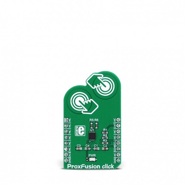
ProxFusion click


Prices incl. GST
Ready to ship today,
Delivery time appr. 1-3 workdays.
1 in stock
- Product Code: MIKROE-2920
- MPN: 2920
ProxFusion click is a multifunctional capacitive and Hall-effect sensor device. This click can detect touch by using two onboard sensor pads, and it can sense a rotation angle of a magnetic field, parallel with the surface of the click board™. The intelligent onboard IC calculates all the parameters and streams the current angle value to the I2C bus directly, without the need for extra calculations.
The integrated circuit, used on ProxFusion click, allows a minimal number of external components, thus allowing the ProxFusion click to work with a very low power consumption. The compact size and advanced onboard functions make this click an ideal solution for implementing all kinds of advanced HMI interfaces, wearable devices, proximity activated or dimmed TFT backlight, digital angle gauges, and similar applications that include any kind of capacitive proximity/touch and Hall-effect sensing elements.
HOW DOES IT WORK?
ProxFusion click carries the IQS624, a combined multi-sensor IC from Azoteq, including Hall-effect rotation sensing, along with dual channel capacitive proximity or touch sensing, or single-channel inductive sensing. This IC features the proven ProxSense® engine and it has many on-chip features that are used to process the sensor data, such as calculated angle rotation with 1° precision, Automatic Tuning Implementation (ATI), relative rotation angle, etc. All these functions are used to process the sensor data, before the final result is sent to the output, in human understandable format. Besides these processed values, the IQS624 is capable of sending raw values on the output too, so that the external processing can be applied.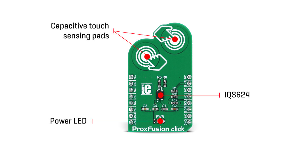
The design of the board is reasonably simple since the IC encompasses all the required components on the chip. The I2C bus lines are pulled up to 3.3V with the resistors, as well as the RDY pin from the IC, routed to the INT pin of the mikroBUS™. This pin can be used to report an event, when the device is set to work in the event mode, via I2C. Otherwise, this pin is used to indicate a communication window. After the host MCU initializes the communication by sending the valid I2C address of the IQS624 IC, it will respond with the ACK signal and the RDY pin will be pulled to a LOW logic state, to indicate an open communication window. I2C features a time-out that will reset the communication bus and the RDY pin, allowing MCU to use interrupts and break the I2C ACK signal polling loop.
The capacitive touch sensing is accomplished by two onboard pads, that are routed to two internal channels of the IQS624 sensor IC. All the calibration can be automatically done by writing to the corresponding ATI registers. This group of registers also contain settings for the capacitive touch threshold, the proximity threshold, as well as some additional general configuration settings for these sensors. Both of these channels can be configured independently.
The rest four channels of the IQS624 sensor are routed to the outputs of two on-chip Hall plates, used to detect a magnetic field rotation. The Hall-effect magnetic field measurement is basically a measurement of the current through the Hall-effect sensor plates, generated by the magnetic field that penetrates through each plate, perpendicularly. The channels 2 and 4 are used to measure positive direction while the channels 3 and 5 are used to measure negative direction. The IC can use the differential data to provide the angle of the Hall-effect rotation UI element - or a magnet rotation angle, parallel to the click board™ surface. The raw input from the sensors is processed so it outputs a comprehensible information at the output. Corresponding registers can be set to both configure and receive the data from Hall-effect sensors.
The working frequency of the device is 16MHz and the maximum I2C clock speed is 400kHz. ProxFusion click can be set to work in several different power saving modes, depending on the design requirements. As explained above, the event mode can be set within the configuration registers. Otherwise, streaming mode is active by default and the information can be obtained whenever the RDY is triggered.
SPECIFICATIONS
| Type | Capacitive |
| Applications | An ideal solution for implementing all kinds of advanced HMI interfaces, wearable devices, proximity activated or dimmed TFT backlight, digital angle gauges, etc. |
| On-board modules | IQS624, a combined multi-sensor IC from Azoteq, including Hall-effect rotation sensing, along with dual channel capacitive proximity or touch sensing, or single-channel inductive sensing |
| Key Features | Low power consumption, compact size, ProxFusion™ sensor series featuring the proven ProxSense® engine. |
| Interface | GPIO,I2C |
| Compatibility | mikroBUS |
| Click board size | M (42.9 x 25.4 mm) |
| Input Voltage | 3.3V |
PINOUT DIAGRAM
This table shows how the pinout on ProxFusion click corresponds to the pinout on the mikroBUS™ socket (the latter shown in the two middle columns).
| Notes | Pin | Pin | Notes | ||||
|---|---|---|---|---|---|---|---|
| AN | 1 | AN | PWM | 16 | NC | ||
| EN | 2 | RST | INT | 15 | INT | RDY indicator | |
| CS | 3 | CS | RX | 14 | NC | ||
| SCK | 4 | SCK | TX | 13 | NC | ||
| NC | 5 | MISO | SCL | 12 | SCL | I2C Clock | |
| SDI | 6 | MOSI | SDA | 11 | SDA | I2C Data | |
| Power Supply | 3V3 | 7 | 3.3V | 5V | 10 | NC | |
| Ground | GND | 8 | GND | GND | 9 | GND | Ground |
PROXFUSION CLICK ELECTRICAL SPECIFICATIONS
| Description | Min | Typ | Max | Unit |
|---|---|---|---|---|
| Maximum continuous current | 10 | mA | ||
| ESD protection | ±4 | kV | ||
| Operating temperature | -20 | 85 | ℃ |
ONBOARD SETTINGS AND INDICATORS
| Label | Name | Default | Description |
|---|---|---|---|
| LD1 | PWR | - | Power LED indicator |
SOFTWARE SUPPORT
We provide a library for ProxFusion click on our Libstock page, as well as a demo application (example), developed using MikroElektronika compilers and mikroSDK. The provided click library is mikroSDK standard compliant. The demo application can run on all the main MikroElektronika development boards.
Library description
Key functions
void proxfusion_systemSetting(uint8_t value)- Sets up system settings
uint8_t proxfusion_Touch()- Reads info about the touch
uint16_t proxfusion_getTemperature() - Reads current temperature
The application is composed of three sections :
- System Initialization - Initializes I2C module and UART for info logging.
- Application Initialization - Driver intialization and ProxFusion mode setup.
- Application Task - (code snippet) - Writes information about the last detected touch.
void applicationTask()
{
touch = proxfusion_Touch();
if( touch == 1 )
mikrobus_logWrite("Touch 1",_LOG_LINE);
if( touch == 2 )
mikrobus_logWrite("Touch 2",_LOG_LINE);
if ( touch == 3 )
mikrobus_logWrite("Touch antenna",_LOG_LINE);
Delay_100ms();
}
The full application code, and ready to use projects can be found on our Libstock page.
Other MikroElektronika Libraries used in the example:
- I2C
- UART
Additional notes and information
Depending on the development board you are using, you may need USB UART click, USB UART 2 click or RS232 click to connect to your PC, for development systems with no UART to USB interface available on the board. The terminal available in all MikroElektronika compilers, or any other terminal application of your choice, can be used to read the message.
MIKROSDK
This click board is supported with mikroSDK - MikroElektronika Software Development Kit. To ensure proper operation of the mikroSDK compliant click board demo applications, mikroSDK should be downloaded from the LibStock and installed for the compiler you are using.
For more information about mikroSDK, visit the official page.