
GNSS RTK Click


Prices incl. GST
Out of Stock.
- Product Code: MIKROE-4456
- MPN: 4456
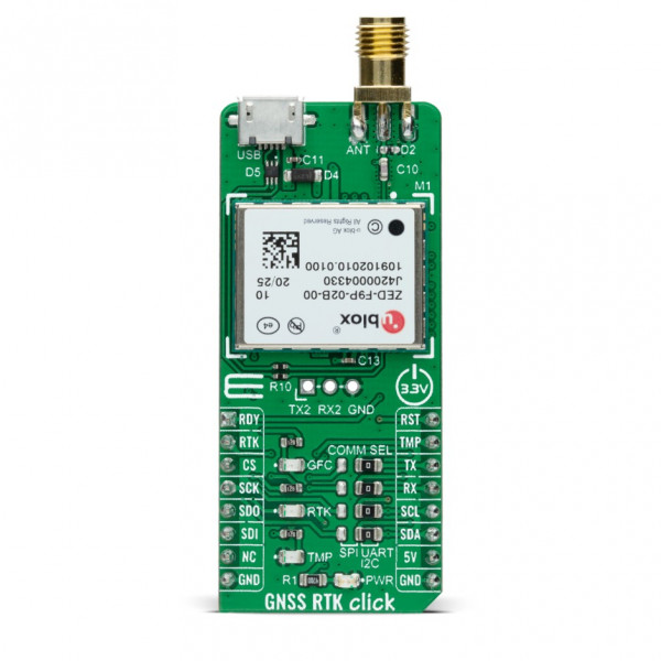
GNSS RTK Click is a compact add-on board used to enhance the precision of position data derived from satellite-based positioning systems. This board features the ZED-F9P, a multi-band GNSS module with integrated multi-band Real Time Kinematics (RTK) technology offering centimeter-level accuracy from U-blox. This module concurrently uses GNSS signals from all four GNSS constellations (GPS, GLONASS, Galileo, and BeiDou), and provides multi-band RTK with fast convergence times, reliable performance, and easy integration. It also includes moving base support, allowing both base and rover to move while computing a centimeter-level accurate position between them. This Click board™ is suitable for machine control, ground robotic vehicles, and high precision unmanned aerial vehicles (UAV) applications.
GNSS RTK Click is supported by a mikroSDK compliant library, which includes functions that simplify software development. This Click board™ comes as a fully tested product, ready to be used on a system equipped with the mikroBUS™ socket.
GNSS RTK Click is based on the ZED-F9P, a multi-band GNSS module with integrated multi-band RTK technology offering centimeter-level accuracy from U-blox. This GNSS receiver can receive and track multiple GNSS constellations. Thanks to the multi-band RF front-end architecture, all four major GNSS constellations (GPS, GLONASS, Galileo, and BeiDou) plus SBAS and QZSS satellites can be received concurrently. The combination of GNSS signals from multiple frequency bands (L1/L2/L5) and RTK technology allows the ZED-F9P to achieve centimeter-level accuracy in seconds. Receiving more satellite signals at any given time maximizes the availability of centimeter-level accuracy even in challenging environments such as in cities.
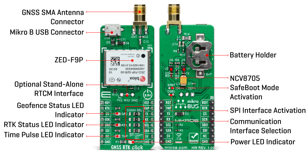
The ZED-F9P comes with built-in support for standard RTCM corrections, routed on the additional header, unpopulated by default, available as an optional stand-alone RTCM input interface that can not be used as a host interface. It also ensures the security of positioning and navigation information by using secure interfaces and advanced jamming and spoofing detection technologies.
GNSS RTK Click communicates with MCU using the UART interface at 9600 bps as its default communication protocol with the option for the users to use other interfaces such as SPI and I2C if they want to configure the module and write the library by themselves. The interface selection between UART/SPI can be performed by positioning SMD jumpers labeled as COMM SEL to an appropriate position. When selecting the SPI communication, with the correct selection of the COMM SEL jumper, it is necessary to set the jumper to DSEL to configure the interface pins as SPI. In the default state, the jumper labeled as DSEL is unpopulated. The receiver also can enter a safe boot mode. If the jumper labeled as SFBT is populated and the SAFEBOOT pin is low at Power-Up, the receiver starts in safe boot mode and GNSS operation is disabled.
The USB interface, compatible with the USB version 2.0 FS (Full Speed, 12 Mbit/s), can be used for communication as an alternative to the UART. The USB port can be used as a power supply if you need the Click board™ to be a standalone device. In the case of the main supply failure, the module can use a backup supply voltage from a connected battery. Backup voltage supplies the real-time clock and battery-backed RAM and enables all relevant data to be saved in the backup RAM to allow a hot or warm start later.
In addition to these features, it also has several GPIO pins. RDY pin routed to the AN pin of the mikroBUS™ socket is used as a communication indicator when bytes are ready to be transmitted, the RST pin routed on the PWM pin of the mikroBUS™ socket provides the ability to reset the receiver, and the TMP pin, with LED indicator, routed on the INT pin of the mikroBUS™ socket provides clock pulses with configurable duration and frequency.
RTK pin routed on the RST pin of the mikroBUS™ socket, alongside with LED indicator labeled as RTK, provides an indication of the RTK positioning status. When LED is blinking, it indicates that a valid stream of RTCM messages is being received, but no RTK fixed mode has been achieved. When the LED is constantly lit, the LED indicates that RTK mode has been achieved. It also has another LED indicator labeled as GDC that indicates the current geofence status as to whether the receiver is inside any of the active areas. This feature can be used, for example, to wake up a sleeping host when a defined geofence condition is reached.
GNSS RTK Click possesses the SMA antenna connector, and it can be used for connecting the appropriate antenna that Mikroe has in its offer, such as GPS Active External Antenna. This antenna is an excellent choice for all GSM/GPRS applications with a frequency range of 1595.42 ± 25MHz.
This Click board™ is designed to be operated only with a 5V logic voltage level. A proper logic voltage level conversion should be performed before the Click board™ is used with MCUs with different logic levels.
Specifications:
| Type | GPS+GNSS |
| Applications | Can be used for machine control, ground robotic vehicles, and high precision unmanned aerial vehicles (UAV) applications |
| On-board modules | GNSS RTK Click is based on the ZED-F9P, a multi-band GNSS module with integrated multi-band RTK technology offering centimeter-level accuracy from U-blox |
| Key Features | High precission, centimeter-level accuracy, high update rate for highly dynamic applications, multi-band RTK with fast convergence times and reliable performance, and more. |
| Interface | GPIO,I2C,SPI,UART,USB |
| Compatibility | mikroBUS |
| Click board size | L (57.15 x 25.4 mm) |
| Input Voltage | 5V |
PinOut Diagram:
This table shows how the pinout on GNSS RTK Click corresponds to the pinout on the mikroBUS™ socket (the latter shown in the two middle columns).
| Notes | Pin | Pin | Notes | ||||
|---|---|---|---|---|---|---|---|
| Transmission Ready Indicators | RDY | 1 | AN | PWM | 16 | RST | Reset |
| RTK Positioning Status | RTK | 2 | RST | INT | 15 | TMP | Configurable Time Pulses |
| SPI Chip Select | CS | 3 | CS | RX | 14 | TX | UART TX |
| SPI Clock | SCK | 4 | SCK | TX | 13 | RX | UART RX |
| SPI Data OUT | SDO | 5 | MISO | SCL | 12 | SCL | I2C Clock |
| SPI Data IN | SDI | 6 | MOSI | SDA | 11 | SDA | I2C Data |
| NC | 7 | 3.3V | 5V | 10 | 5V | Power Supply | |
| Ground | GND | 8 | GND | GND | 9 | GND | Ground |
OnBoard Settings And Indicators:
| Label | Name | Default | Description |
|---|---|---|---|
| LD1 | PWR | - | Power LED Indicator |
| LD2 | TMP | - | Time Pulse LED Indicator |
| LD3 | RTK | - | RTK Status LED Indicator |
| LD4 | GFC | - | Geofence Status LED Indicator |
| JP1-JP4 | COMM SEL | Left | Communication Interface Selection SPI/UART: Left position SPI, Right position UART |
| J1 | - | Unpopulated | Optional Stand-Alone RTCM Interface |
| J5 | DSEL | Unpopulated | SPI Interface Activation |
| J6 | SFBT | Unpopulated | SafeBoot Mode Activation |
GNSS RTK Click Electrical Specifications:
| Description | Min | Typ | Max | Unit |
|---|---|---|---|---|
| Supply Voltage | - | 5 | - | V |
| Backup Supply Voltage | 1.65 | - | 3.6 | V |
| Position Accuracy | - | 10 | - | mm |
| Operating Frequency | 1.2276 | - | 1.575 | GHz |
| Maximum Output Current | - | - | 100 | mA |
| Maximum Altitude | - | - | 50 | km |
| Maximum Velocity | - | - | 500 | m/s |
| Operating Temperature Range | -40 | - | +85 | °C |
Software Support:
We provide a library for the GNSS RTK Click as well as a demo application (example), developed using MikroElektronika compilers. The demo can run on all the main MikroElektronika development boards.
Package can be downloaded/installed directly from NECTO Studio Package Manager(recommended way), downloaded from our LibStock™ or found on mikroE github account.
Library Description
This library contains API for GNSS RTK Click driver.
Key functions:
void gnssrtk_cfg_setup ( gnssrtk_cfg_t *cfg );- Config Object Initialization function.GNSSRTK_RETVAL gnssrtk_init ( gnssrtk_t *ctx, gnssrtk_cfg_t *cfg );- Initialization function.void gnssrtk_default_cfg ( gnssrtk_t *ctx );- Click Default Configuration function.
Examples description
This example reads and processes data from GNSS RTK click.
void application_task ( void ) {
gnssrtk_process();
parser_application( current_parser_buf );
}
The full application code, and ready to use projects can be installed directly from NECTO Studio Package Manager(recommended way), downloaded from our LibStock™ or found on mikroE github account.
Other mikroE Libraries used in the example:
- MikroSDK.Board
- MikroSDK.Log
- Click.GNSSRTK
Additional notes and informations
Depending on the development board you are using, you may need USB UART click, USB UART 2 click or RS232 click to connect to your PC, for development systems with no UART to USB interface available on the board. The terminal available in all MikroElektronika compilers, or any other terminal application of your choice, can be used to read the message.
MikroSDK:
This Click board™ is supported with mikroSDK - MikroElektronika Software Development Kit. To ensure proper operation of mikroSDK compliant Click board™ demo applications, mikroSDK should be downloaded from the LibStock and installed for the compiler you are using.
For more information about mikroSDK, visit the official page.
Resources:
Downloads:
GNSS RTK click example on Libstock