
TI-RSLK Chassis Board v1.0 for TI-RSLK MAX


Prices incl. GST
Ready to ship today,
Delivery time appr. 1-3 workdays.
4 in stock
- Product Code: Pololu-3671
- MPN: 3671
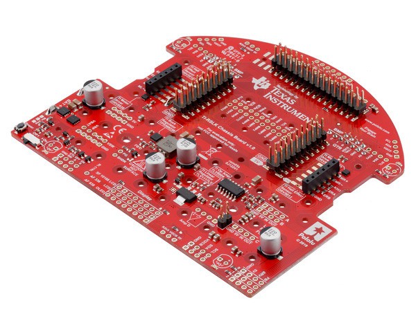
This is the main board for the Pololu Chassis Kit for TI-RSLK MAX, made available for replacements. It ships with the single battery contacts already soldered in, so no soldering is required to use it. Four #2-56 3/16″ screws and nuts are included for mounting the board to the Romi chassis.
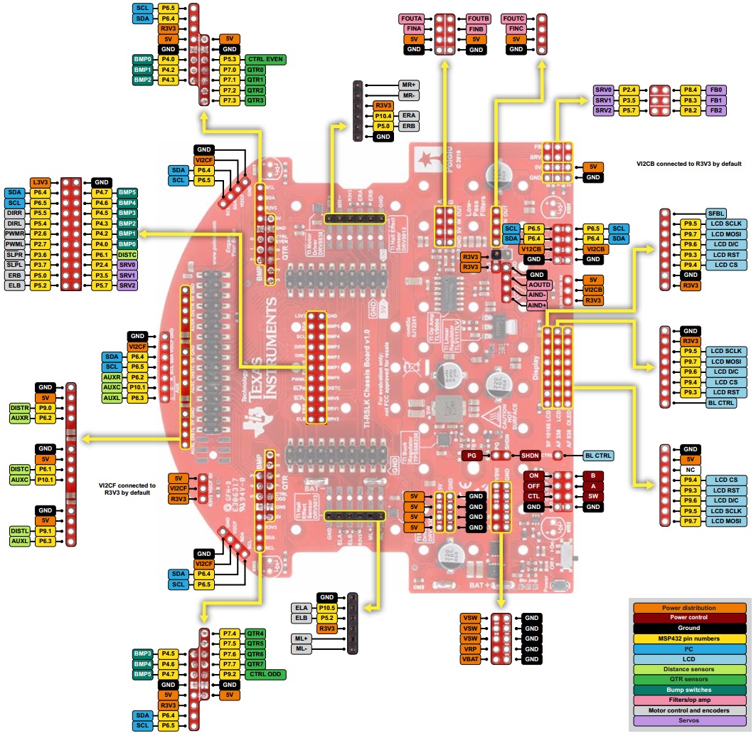
Pinout diagram
 |
Operating voltage range
The TI-RSLK Chassis Board v1.0 for TI-RSLK MAX is generally intended to be powered by six AA batteries, either alkaline or rechargeable, but the board can handle input voltages up to 10.8 V. The minimum input voltage is subject to the dropout voltage characteristics of the on-board 5 V switching regulator, which depend on the load on the 5V rail as shown in the dropout voltage graph below. With no additional load on the 5V rail, the minimum input needed to get 5 V out is about 5.2 V. This increases approximately linearly to around 5.8 V with 7 A of load.
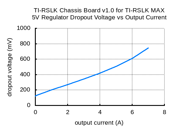 |
Note that none of the features of the TI-RSLK MAX actually need the 5V rail to be at 5 V, so if nothing else sensitive is connected to that rail, the input voltage to the chassis board can drop as low as 4.5 V before the board stops functioning.
Power
The TI-RSLK Chassis Board includes battery terminal connections that provide access to power from the chassis’s six-AA battery compartment. We recommend using rechargeable AA NiMH cells, which results in a nominal voltage of 7.2 V (1.2 V per cell). You can also use alkaline cells, which would nominally give you 9 V.
The negative battery voltage is connected to GND. The positive battery voltage is designated VBAT. VBAT feeds into a reverse protection circuit and then a power switching circuit controlled by the on-board pushbutton or slide switch. The output of the power switching circuit is designated VSW.
VSW provides power to the motors through the on-board DRV8838 motor drivers, so the motors can only operate if the batteries are installed and the power switch circuit is on.
Power switch circuit
TI-RSLK Chassis Board uses the patented latching circuit from the Pololu pushbutton power switch, which provides a solid-state power switch for your robot controlled with the on-board pushbutton. By default, this pushbutton can be used to toggle power: one push turns on power and another turns it off. Alternatively, a separate pushbutton can be connected to the A and B pins and used instead. Multiple pushbuttons can be wired in parallel for multiple control points, and each of the parallel pushbuttons, including the one on the board itself, will be able to turn the switch on or off. The latching circuit performs some button debouncing, but pushbuttons with excessive bouncing (several ms) might not function well with it.
For proper pushbutton operation, the board’s slide switch should be left in its Off position. (Sliding the switch to the On position will cause the board power to latch on, and the switch must be returned to the Off position before the board can be turned off with the pushbutton.)
Alternatively, to disable the pushbutton, you can cut the button jumper labeled Btn Jmp; this transfers control of the board’s power to the on-board slide switch instead. A separate slide or toggle switch can be connected to the SW pin and used instead.
The power switch circuit also offers several alternate pushbutton connection options that result in push-on-only or push-off-only operation, and additional inputs enable further power control options like allowing your robot to turn off its own power. These advanced control options are available through the button connection pins and four control inputs:
| PIN | Description |
|---|---|
| A | Connect through momentary switch to pin “B” for standard push-on/push-off operation. Connect through momentary switch to ground for on-only operation. |
| B | Connect through momentary switch to pin “A” for standard push-on/push-off operation. |
| ON | A high pulse (> 1 V) on this pin turns on the switch circuit. This pin only functions when pushbutton operation is enabled (i.e. the button jumper has not been cut). |
| OFF | A high pulse (> 1 V) on this pin turns off the switch circuit (e.g. allowing a powered device to shut off its own power). This pin only functions when pushbutton operation is enabled. |
| CTRL | With pushbutton operation enabled, this pin directly determines the state of the switch circuit. A high pulse (> 1 V) on this pin turns on the switch; a low pulse (e.g. driving the pin low with a microcontroller output line or pushing a button connected from this pin to ground) turns the switch off. Leave this pin disconnected or floating when not trying to set the switch state. Note that this pin should not be driven high at the same time the “OFF” pin is driven high. |
| SW | With pushbutton operation disabled (button jumper cut), this pin controls the state of the switch circuit: driving it low turns the switch on, while letting it float turns the switch off. Connect through slide or toggle switch to ground for on/off operation. Leave this pin disconnected or floating for proper pushbutton operation. We recommend only ever driving this pin low or leaving it floating; this pin should never be driven high while the slide switch is in the “On” position. |
General specifications
| Minimum operating voltage: | 5.2 V1 |
|---|---|
| Maximum operating voltage: | 10.8 V |
Notes:
Subject to dropout voltage considerations. See the dropout voltage graph under the description tab for more information.