
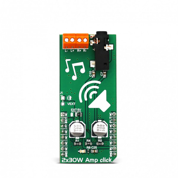
2x30W Amp click


Prices incl. GST
Ready to ship today,
Delivery time appr. 1-3 workdays.
1 in stock
- Product Code: MIKROE-3010
- MPN: 3010
2x30W Amp click is a class-D audio amplifier with a tremendous output power, considering its size and lack of huge heatsinks, usually associated with the audio amplifiers. This is due to the fact that the efficiency of the amplifier IC is quite high (greater than 90%), featuring the efficiency boost mode, which dynamically reduces the current ripple of the external LC filter and current in idle mode. The integrated self-protection circuits include overvoltage, undervoltage, and overtemperature protection, output DC offset detection, as well as the short circuit detection, with the error reporting feature, via the dedicated pin.
With the power efficiency and low power consumption in mind, the 2x30W Amp click is a perfect solution for battery powered active speakers. Due to a low idle current, as low as 25mA, the battery power consumption is greatly reduced, especially when the amplifier is idling. Equipped with all these features, 2x30W Amp is an ideal tool for building various audio applications that require an output amplification with very low noise and distortion (THD), such as wireless Bluetooth speakers, home theater systems, mini and micro audio components, and similar.
How does it work?
The main component of the 2x30W Amp click is TPA3128, 2x30-W class-D amplifier with low idle power dissipation, from Texas Instruments. The most important characteristic of this IC is its output efficiency, which reduces the need for bulky heat sinks, usually associated with the audio amplifiers. This is accomplished by using switching MOSFET outputs, which have very low RDSON, as low as 90 mΩ.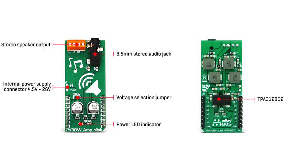
Unlike class A or class AB amplifiers, class D amplifiers are way more efficient, by design. Class D amplifier working principles are based on the switching characteristic of the transistors, rather than the linear characteristic, used for the A/AB class amplifiers. The audio signal is encoded into a PWM signal with the fixed amplitude. An output signal is restored by running it through the LC filter and the speaker itself. Since the basis of this principle is switching of the signal, and the transistors are either fully ON or fully OFF, they spend very little time in the linear region, and dissipate very little power. Using low RDSON MOSFETs becomes possible and desirable so that the efficiency goes up to 90% and over.
2x30W Amp click is designed to work with 2 channels of a single-sided audio source, connected via the 3.5mm stereo audio jack, which is provided on board.
The Click board™ is equipped with a connector for the external power source. By default, the 2x30 Amp click is supplied via the mikroBUS™ 5V rail, which limits the output power. For the full output power, an adequate external power supply should be used. The TPA3128 IC can handle up to 26V. To select operation via the external power supply, the onboard SMD jumper should be switched to the desired position (EXT or 5V). If EXT position is selected, the external power supply should be connected via the 2x1 header on the side of the Click board™, labeled as VEXT.
The connected speaker impedance should not be less than 4Ω. The speakers can be connected via two edge connectors, with clearly labeled input ports: L+ and L- for connecting the left speaker positive and negative terminals; R+ and R- for connecting the right speaker positive and negative terminals. Care should be taken to dimension the speakers according to the maximum output power of the amplifier.
The amplifier has fixed gain of 32dB, determined by two resistors, labeled as R4 and R5 on the provided schematic.
The RST pin of the mikroBUS™ is routed to the SDZ pin of the TPA3128 IC. Setting this pin to a LOW logic level will set the TPA3128 IC in the shutdown mode, with its output stage set to a high impedance (Hi-Z), reducing the idle current to a minimum. It is a good practice to pull the SDZ (RST) pin to a LOW logic level before disconnecting the power from the Click board™ to avoid audible power-off clicks. RST pin is pulled up to a HIGH logic level by the onboard resistor.
Another way to mute the speakers is pulling the MUTE pin to a HIGH logic level. This pin is routed to the CS pin of the mikroBUS™ and it is labeled as the MT. Pulling this pin to a HIGH logic level will also set the output stage to a Hi-Z, but it will perform muting function only, thus muting the IC faster than the complete shutdown with the SDZ pin. This function is useful if used in conjunction with the FAULT pin, allowing power-up in a muted state when there is a problem on the output stage.
FAULTZ pin is routed to the INT pin of the mikroBUS™ and it is labeled as the FLT. It is used to signalize the fault condition (overtemperature, output DC offset detection) to the host MCU. It is active low and can be used to trigger an interrupt request on the host MCU so that the proper action can be taken.
The Click board™ uses only GPIO pins, so the usage is extremely simple. However, the Click board™ comes with the library that contains functions for the mikroC, mikroBASIC and mikroPASCAL compilers, which simplify using this Click board™ even more. The provided example application demonstrates their use and it can be used as a reference for a custom design.
Specifications
| Type | Amplifier |
| Applications | Various audio applications that require an output amplification with very low noise and distortion (THD), such as wireless Bluetooth speakers, home theater systems, mini and micro audio components, and similar. |
| On-board modules | TPA3128, 2x30-W class-D amplifier with low idle power dissipation, from Texas Instruments |
| Key Features | High output power with reasonably low voltage and no heat sinks, low THD and SNR, integrated short circuit detection, output DC offset detection, overvoltage, undervoltage, and overtemperature protection |
| Interface | GPIO |
| Input Voltage | 5V |
| Click board size | L (57.15 x 25.4 mm) |
Pinout diagram
This table shows how the pinout on 2x30W Amp click corresponds to the pinout on the mikroBUS™ socket (the latter shown in the two middle columns).
| Notes | Pin | Pin | Notes | ||||
|---|---|---|---|---|---|---|---|
| NC | 1 | AN | PWM | 16 | NC | ||
| Reset/SDZ IN | RST | 2 | RST | INT | 15 | FLT | FAULTZ OUT |
| Mute IN | MT | 3 | CS | RX | 14 | NC | |
| NC | 4 | SCK | TX | 13 | NC | ||
| NC | 5 | MISO | SCL | 12 | NC | ||
| NC | 6 | MOSI | SDA | 11 | NC | ||
| NC | 7 | 3.3V | 5V | 10 | +5V | Power supply | |
| Ground | GND | 8 | GND | GND | 9 | GND | Ground |
2x30W Amp electrical characteristics
| Description | Min | Typ | Max | Unit |
|---|---|---|---|---|
| External PSU Voltage | 4.5 | 26 | V | |
| Minimum load Impedance | 4 | Ω | ||
| Continuous output power | 30 | W | ||
| Total Harmonic Distortion (THD) at P = 15W | 0.1 | % | ||
| Signal-to-Noise Ratio (SNR) | 102 | dB |
Onboard settings and indicators
| Label | Name | Default | Description |
|---|---|---|---|
| LD1 | PWR | - | Power LED indicator |
| JP1 | EXT / 5V | Right | Power supply selection: left position external PSU, right position 5V |
| CN1 | - | - | 3.5mm stereo jack for audio input |
| TB2 | L- L+ | - | Left speaker connector |
| TB4 | R+ R- | - | Right speaker connector |
Software support
We provide a library for 2x30W Amp click on our Libstock page, as well as a demo application (example), developed using MikroElektronika compilers. The demo application can run on all the main MikroElektronika development boards.
Library Description
The library allows the device to be enabled or disabled and allows the mute and the unmute operation. The library also has the ability to check fault condition (over current, over temperature and too high DC offset condition).
For more details check the documentation.
Key functions:
void c2x30wamp_enable( uint8_t state )- The function allows the device to be enabled or disabled.void c2x30wamp_mute( uint8_t state )- The function performs the mute or the unmute operation.uint8_t c2x30wamp_checkDiagnostic( void )- The function checks if the device in a fault condition or in a normal operation state.
Examples Description
The demo application is composed of three sections:
- System Initialization - Initializes peripherals and pins.
- Application Initialization - Initializes GPIO driver and allows the device to be enabled.
- Application Task - (code snippet) - Allows the mute operation for a period of 4 seconds,
and after that allows the unmute operation for a period of 10 seconds. After that time, it checks if the overcurrent fault, over temperature fault or too high DC offset fault occurred.
Note: When under or overvoltage condition occurs the output goes to high impedance state,
but the FAULT pin will not be asserted.
void applicationTask()
{
c2x30wamp_mute( _C2X30WAMP_MUTE );
Delay_ms( 4000 );
c2x30wamp_mute( _C2X30WAMP_UNMUTE );
Delay_ms( 10000 );
faultCheck = c2x30wamp_checkDiagnostic();
if (faultCheck == 0)
{
mikrobus_logWrite( "Fault condition!", _LOG_LINE );
}
}
The full application code, and ready to use projects can be found on our Libstock page.
mikroE Libraries used in the example:
- UART
Additional notes and information
Depending on the development board you are using, you may need USB UART click, USB UART 2 click or RS232 click to connect to your PC, for development systems with no UART to USB interface available on the board. The terminal available in all MikroElektronika compilers, or any other terminal application of your choice, can be used to read the message.
mikroSDK
This click board is supported with mikroSDK - MikroElektronika Software Development Kit. To ensure proper operation of mikroSDK compliant click board demo applications, mikroSDK should be downloaded from the LibStock and installed for the compiler you are using.
For more information about mikroSDK, visit the official page.
Downloads
mikroBUS™ Standard specification
LibStock: mikroSDK
TPA3128D2 datasheet