Prices incl. GST
Out of Stock.
- Product Code: MIKROE-2477
- MPN: MIKROE-2477
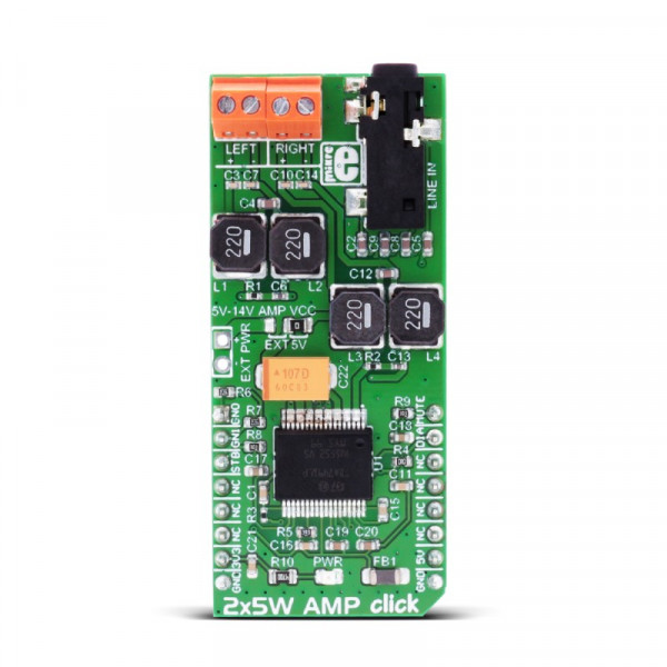
2x5W AMP click functions as an amplifier and features the TDA7491LP 2x5-watt dual BTL class-D audio amplifier. The click is designed to run on either 3.3V or 5V power supply. It communicates with the target MCU over the following pins on the mikroBUS™ line: AN, RST, CS, PWM, INT.
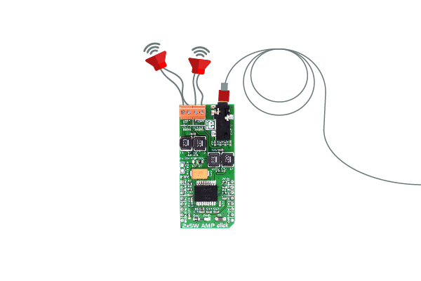
2x5W AMP click features a 3.5mm input jack and four output screw terminals for connecting passive speakers.
Note: In order to achieve full 2x5W output power, keep in mind that you need to supply enough current to the chip.
This is achievable with the EXT PWR header, but you need to switch over the AMP VCC to the left position.
Note: a 3.5mm stereo cable and wired passive speakers are not included in the offer.

Class-D audio amplifier
Class-D audio amplifiers (switching amplifiers) are very energy efficient. They reduce power losses on the output device by operating as an electronic switch, rather than as linear gain devices, like in A or AB amplifiers.
These kinds of amplifiers are ideal for compact, high power applications.
TDA7491LP audio amplifier
The amplifier has three operating modes:
Standby mode: all circuits are turned off, very low current consumption. The amplifier uses a maximum of 10uA in standby mode.
Mute mode: inputs are connected to ground and the positive and negative PWM outputs are at 50% duty cycle.
Play mode: the amplifiers are active.
Simple control
The click does not use a standard serial communication, like I2C or SPI - it's controlled by a few pins on the mikroBUS™ line. The state of these pins can either be HIGH or LOW (mute, gain, enable). The operating modes and gain are set with input pins.
Specifications
| Type | Amplifier |
| Applications | Mobile phones, portable sound systems, etc. |
| On-board modules | TDA7491LP 2x5-watt dual BTL class-D audio amplifier |
| Key Features | 2x5W output power, short-circuit protection, thermal overload protection, 3.5mm audio jack, screw terminals for passive speakers. |
| Interface | GPIO |
| Input Voltage | 3.3V or 5V |
| Compatibility | mikroBUS |
| Click board size | L (57.15 x 25.4 mm) |
Pinout diagram
This table shows how the pinout on 2x5W AMP click corresponds to the pinout on the mikroBUS™ socket (the latter shown in the two middle columns).
Jumpers and settings
| Designator | Name | Default Position | Default Option | Description |
|---|---|---|---|---|
| JP1 | AMP VCC | Right | 5V | AMP power supply, can be 5V or external (5V-14V) |
LEDs, buttons, connectors and switches
| Designator | Name | Type (LED, BUTTON...) | Description |
|---|---|---|---|
| EXT PWR | EXT PWR | Connector | two pin non-populated headerfor the external Amp supply |
Programming
The library has two helper functions for setting the gain and the mode via output pins.
Code snippet
The demo shows how to initialize, set the mode and the gain of the click.
01 void main()
02 {
03     system_init();
04
05     click_2x5W_gain(CLICK_2X5W_AMP_20_DB);
06     click_2x5W_mode(CLICK_2X5W_AMP_MODE_PLAY);
07
08     while( 1 )
09     {
10         if(Button(&GPIOE_IDR, 11, 100, 1))
11         {
12             click_2x5W_gain((click_2x5w_amp_gain_t)(++gain % 4));
13         }
14     }
15 }


