
USB UART click


Prices incl. GST
Out of Stock.
- Product Code: MIKROE-1203
- MPN: MIKROE-1203
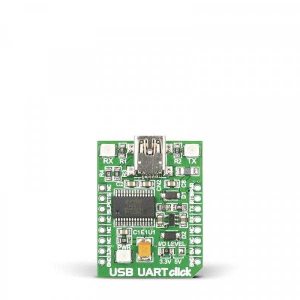
USB UART click offers a USB to asynchronous serial data (UART) interface, allowing the microcontroller based designs to communicate with the personal computer, in a very simple way. It is equipped with the FT232RL, a very popular USB to UART interface IC, used on many MikroElektronika devices - both for its reliability and simplicity. USB UART click is used for whenever there is a need for seamless and effortless interfacing of the UART lines to a personal computer. It can be used with any UART terminal, like the one found in MikroElektronika compilers.
How does it work?
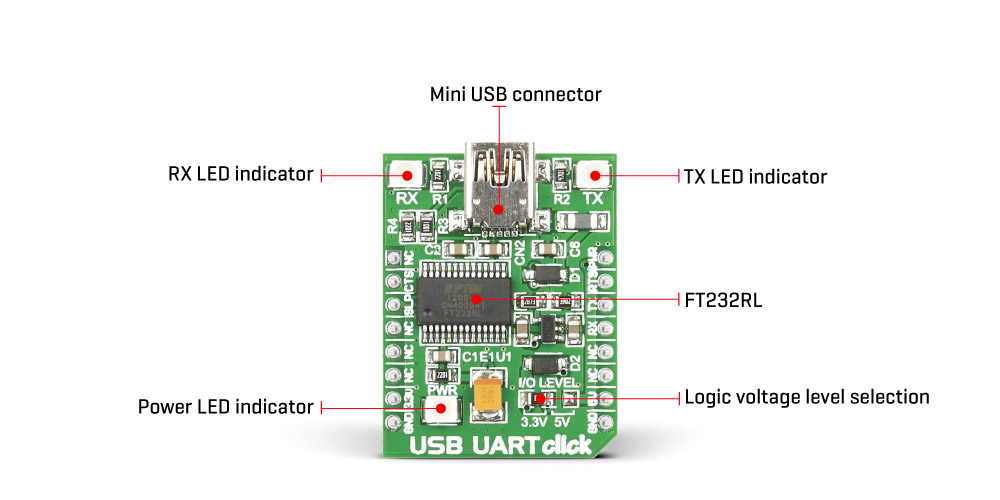
Like already mentioned, USB UART click carries the FT232RL, a USB to UART interface IC, from FTDI. The entire USB protocol is handled on the IC itself, thus no USB specific firmware programming is required. FTDI provides royalty-free Virtual Com Port (VCP) and Direct (D2XX) drivers for all the major OSes, used on personal computers. FT232RL also contains an integrated 1024 Bit internal EEPROM for storing USB VID, PID, serial number, product description strings and CBUS I/O configuration.
The Baud Rate Generator provides a 16x clock input to the UART Controller from the 48MHz reference clock. It consists of a 14-bit pre-scaler and 3 register bits which provide fine tuning of the baud rate - used to divide by a number plus a fraction. This determines the baud rate of the UART, which is programmable from 183 baud to 3 Mbaud. Also, non-standard baud rates are supported. The baud rate is automatically calculated by the FTDI driver, so it is enough to simply forward the desired baud rate to the driver, usually done by selecting the baud rate via the GUI interface of the PC terminal application.
After installing the OS drivers, the device is ready to be used. When plugged in, it will create a virtual COM port. After that, it can be used with the USART Terminal application, included in every mikroE compiler. It can be used for the data exchange between the MCU and the host computer. The USB UART click is equipped with the mini USB connector, allowing easy interfacing with the USB port of the host device. More information about working with the UART communication, in general, can be found in the Learn article.
This device also features the configurable CBUS pins, which can be used for several different useful functions, as for example - configurable clock out for driving the microcontroller, data LED drive, USB Sleep, PWR status and so on. By default, CBUS3 and CBUS4 pins are configured as Power Enable and Sleep options and are routed to the PWM and CS pins of the mikroBUS™, respectively. More information about configuring the CBUS pins can be found in the FT232RL datasheet.
CBUS3 output pin (PWM pin of the mikroBUS™) will be set to a LOW logic state during the USB suspend mode It can be used to power down external circuitry or be used for similar purposes.
CBUS4 output pin (CS pin of the mikroBUS™) will be set to a LOW logic state after the device has been configured by the USB, then HIGH during the USB suspend mode. This can also be used for the powering down/power saving, by turning unneeded external circuitry.
This device also supports two additional signals - RTS (Request To Send) and CTS (Clear To Send), which can be used when the hardware flow control is required.
USB UART click also features a small low noise LDO, used to provide the logic voltage level reference. The input voltage for the LDO is taken from the USB or the mikroBUS™ 5V rail. The 3.3V rail from the LDO output is routed to the SMD jumper, labeled as the I/O LEVEL. It allows selection of the referent voltage for the logic section of the FT232RL, providing conditions to interface the USB UART click to both 3.3V and 5V MCUs.
The UART communication is indicated by two LEDs, red for TX (sending data in UART to USB direction) and yellow for RX (receiving data in USB to UART direction). These LEDs are used to provide a visual indication if there is any data transfer ongoing.
Specifications
| Type | USB |
| Applications | Board is used in RS232 communication with modems, printers, PC applications, and various devices that use UART communication protocol |
| On-board modules | FT232RL USB-to-UART interface module |
| Key Features | The FT232RL contains integrated 1024 bit EEPROM, 128 bytes long receive buffer, 256 bytes long transmit buffer |
| Key Benefits | Configurable CBUS I/0 pins and entire USB protocol handled on the chip. |
| Interface | GPIO,UART,USB |
| Input Voltage | 3.3V or 5V |
| Compatibility | mikroBUS |
| Click board size | S (28.6 x 25.4 mm) |
Pinout Diagram
This table shows how the pinout on USB UART click corresponds to the pinout on the mikroBUS™ socket (the latter shown in the two middle columns).
| Notes | Pin | Pin | Notes | ||||
|---|---|---|---|---|---|---|---|
| NC | 1 | AN | PWM | 16 | PWR | Power enable / CBUS3 | |
| Sleep / CBUS4 | SLP | 2 | RST | INT | 15 | RTS | Request to send |
| Clear to send | CTS | 3 | CS | RX | 14 | TX | Transmit |
| NC | 4 | SCK | TX | 13 | RX | Receive | |
| NC | 5 | MISO | SCL | 12 | NC | ||
| NC | 6 | MOSI | SDA | 11 | NC | ||
| Power supply | +3.3V | 7 | 3.3V | 5V | 10 | +5V | Power supply |
| Ground | GND | 8 | GND | GND | 9 | GND | Ground |
USB UART 4 Click Electrical Specifications
| Description | Min | Typ | Max | Unit |
|---|---|---|---|---|
| Logic voltage level | 3.3 | 5.25 | V | |
| Operating temperature | -40 | 85 | °C |
Onboard Settings And Indicators
| Label | Name | Default | Description |
|---|---|---|---|
| LD1 | RX LED | - | Data Send (RX) status LED |
| LD2 | TX LED | - | Data Receive (TX) status LED |
| LD3 | PWR | - | Power LED indicator |
| JP1 | I/O LEVEL | Left | Logic voltage level selection: left position 3.3V, right position 5V |
Software Support
We provide an example for USB UART click inside all of our compilers. You can navigate to the demo using Project Explorer placed inside the folder named same as your development system.
Examples Description
Example application acts as a simple echo and each character is sent using the available terminal in all MikroElektronika compilers. Also, any other terminal of your choice can be used to write and read the messages.
char uard_rd;
void main()
{
UART1_Init(9600);               // Initialize UART module at 9600 bps
Delay_ms(100);                  // Wait for UART module to stabilize
UART1_Write_Text("Start");
UART1_Write(13);
UART1_Write(10);
while (1)
{
if (UART1_Data_Ready())
{
uart_rd = UART1_Read();     // read the received data,
UART1_Write(uart_rd);       // and send data via UART
}
}
}
Downloads
mikroBUS™ Standard specification