
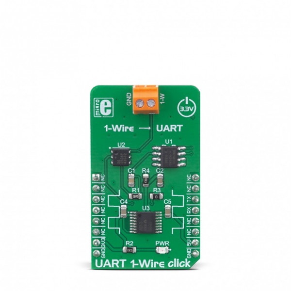
UART 1-Wire Click


Prices incl. GST
Out of Stock.
- Product Code: MIKROE-3340
- MPN: MIKROE-3340
Featuring a set of options for fine-tuning the 1-Wire® bus performance, allowing it to accommodate to a wide variety of different applications, complex state machine which allow straight-forward conversion of characters sent over the UART interface, using the accurate crystal-driven UART timing as a reference for the 1-Wire® time base, UART 1-Wire click represents a perfect solution for rapid development of 1-Wire® applications: it can be used to facilitate working with various iButton® devices or similar applications based on 1-Wire® communication, offering a simple and familiar UART interface to the host microcontroller (MCU).
About the 1-Wire® protocol
1-Wire® is a very popular communication protocol developed by Dallas Semiconductors (acquired by Maxim Integrated in 2001), that requires only two wires: signal line and GND. In most cases GND is common to both devices, so the whole bus is reduced to just a single line. The 1-Wire®protocol is often used between different devices when low-speed communication is sufficient. With the appearance of iButton® devices and MicroLAN interfaces, the 1-Wire® protocol gains popularity. However, there are not many MCUs that have the 1-Wire® peripheral integrated onboard, so they must rely on bit-banging routines to provide accurate 1-Wire® signal waveforms. Producing accurately timed signals by using such routines may prove demanding for most applications. Because of this, devices such as UART 1-Wire click simplify the firmware development greatly, reducing the host MCU workload.
How does it work?
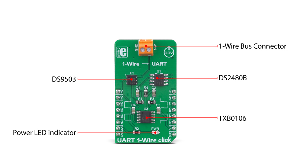
UART 1-Wire click is based on the DS2480B IC, a serial to the 1-Wire® driver IC, from Maxim Integrated. This IC is designed to directly interface the UART with the 1-Wire® bus. It performs data conversion using independent data rates for both interfaces, allowing standard and overdrive communication speeds. Internal timing generators of the DS2480B IC are continuously synchronized with the incoming UART data, which is typically driven by a high-precision crystal oscillator of the host microcontroller (MCU). This allows time-critical 1-Wire® signals to be generated by the IC itself, greatly reducing the processing load from the host MCU. Many physical parameters of both the UART and 1-Wire® buses can be fine-tuned so that the UART 1-Wire click can be accommodated to any type of UART/RS232 to 1-Wire® signal conversion application.
The DS2480B IC can be observed as a complex state-machine. It can be configured by UART commands, so the IC must parse the incoming data prior to conversion. The device can be operated in two main operating modes: Command Mode and Data Mode. The Command Mode is the default state after the Power ON event. This mode allows the configuration parameters to be set. However, the DS2480B IC must be initialized prior to any operation: the 1-Wire® bus reset command should be sent over the TXD line at a fixed rate of 9600 bps. This is used only to calibrate the internal timing generators, without performing any action on the 1-Wire® bus. After the initialization, the DS2480B IC can be used normally.
The Data Mode is used to convert bytes received at the TXD line into their equivalent 1-Wire® waveforms, and to report the responses back to the host MCU through the RXD line. The datasheet of the DS2480B IC illustrates the operating principles of this IC by using the state transition diagram. Along with several examples at the end of the datasheet, it represents a very useful starting point for the application development. However, the included mikroSDK compatible library offers functions that simplify the firmware development even more.
The DS2480B IC requires using 5V for both the power supply and logic levels. Having in mind that most MCUs use 3.3V logic levels for UART communication, a level translator had to be added. UART 1-Wire click uses the TXB0106, a bi-directional level translator IC, by Texas Instruments. This IC allows reliable logic voltage level translation, allowing the Click board™ to be used with a wide range of MCUs that use 3.3V logic levels on their UART lines.
The 1-Wire® bus can be accessed over the screw terminal on the Click board™. Due to the nature of most 1-Wire® applications, the signal line of the 1-Wire® bus is protected by the DS9503, an integrated ESD Protection Diode with resistors. This IC is specifically designed to be used as the Electrostatic Discharge (ESD) protection in 1-Wire® applications.
Specifications
| Type | 1-Wire |
| Applications | The Click board™ can be used to facilitate working with various iButton® devices or similar applications based on 1-Wire communication, offering a simple and familiar UART interface to the host microcontroller (MCU) |
| On-board modules | DS2480B IC, a serial to 1-Wire driver IC, from Maxim Integrated; TXB0106, a bi-directional level translator IC, by Texas Instruments |
| Key Features | A set of options for fine-tuning the 1-Wire bus performance, complex state machine which allow straight-forward conversion of characters sent over the UART interface, an accurate 1-Wire bus timing derived from the crystal-driven UART reference, etc. |
| Interface | UART |
| Input Voltage | 3.3V,5V |
| Click board size | M (42.9 x 25.4 mm) |
Pinout diagram
This table shows how the pinout on UART 1-Wire click corresponds to the pinout on the mikroBUS™ socket (the latter shown in the two middle columns).
| Notes | Pin | Pin | Notes | ||||
|---|---|---|---|---|---|---|---|
| NC | 1 | AN | PWM | 16 | NC | ||
| NC | 2 | RST | INT | 15 | NC | ||
| NC | 3 | CS | RX | 14 | TX | UART TXD Line | |
| NC | 4 | SCK | TX | 13 | RX | UART RXD Line | |
| NC | 5 | MISO | SCL | 12 | NC | ||
| NC | 6 | MOSI | SDA | 11 | NC | ||
| Power Supply | 3V3 | 7 | 3.3V | 5V | 10 | 5V | Power Supply |
| Ground | GND | 8 | GND | GND | 9 | GND | Ground |
Onboard settings and indicators
| Label | Name | Default | Description |
|---|---|---|---|
| PWR | PWR | - | Power LED indicator |
| CN1 | GND, 1-W | - | 1-Wire® bus connector |
Software support
We provide a library for the UART 1-Wire Click on our LibStock page, as well as a demo application (example), developed using MikroElektronika compilers. The demo can run on all the main MikroElektronika development boards.
Library Description
The library initializes and defines the UART bus driver and drivers that offer a choice for writing data on UART. The library includes the function for reading data and functions for go to Command/Data mode. The user also has the function for reset chip and storage read data.
Key functions:
void uart1wire_writeCommand(uint8_t input)- Functions for write one byte on UART.uint8_t uart1wire_readByte()- Functions for read byte from UART.void uart1wire_goToCommandMode()- Functions for go to command mode.void uart1wire_goToDataMode()- Functions for go to data mode.void uart1wire_readData(uint8_t *buf, uint8_t nData)- Functions for read data.
Examples description
The application is composed of the three sections :
- System Initialization - Initializes UART module.
- Application Initialization - Initializes Driver init, interrupt routine and init thermo 2 click.
- Application Task - (code snippet) - Reads the temperature from the Thermo 2 click board and logs data to UART. Connection between Thermo 2 and UART 1 Wire is made through 1- Wire interface. You can place thermo 2 click on mikrobus 2 socket and use side headers to make connection between click boards.
void applicationTask()
{
/* Start converzion */
uart1wire_reset();
uart1wire_goToDataMode();
Delay_10ms();
uart1wire_writeCommand(_UART1WIRE_SKIP_ROM);
uart1wire_writeCommand( 0x44 );
Delay_ms( 750 );
/* Start reading temperature */
uart1wire_reset();
uart1wire_goToDataMode();
Delay_10ms();
uart1wire_writeCommand(_UART1WIRE_SKIP_ROM);
uart1wire_writeCommand( 0xBE );
Delay_10ms();
uart1wire_readData(&dataBuffer[0], 8);
Temp = dataBuffer[ 1 ];
Temp = Temp << 8;
Temp = Temp | dataBuffer[ 0 ];
fTemp = Temp * 0.0625;
mikrobus_logWrite(" Temperature : ", _LOG_TEXT);
FloatToStr(fTemp, demoText);
mikrobus_logWrite(demoText, _LOG_LINE);
Delay_ms( 1000 );
}
The full application code, and ready to use projects can be found on our LibStock page.
Other mikroE Libraries used in the example:
UARTConversions
Additional notes and information
Depending on the development board you are using, you may need USB UART click, USB UART 2 click or RS232 click to connect to your PC, for development systems with no UART to USB interface available on the board. The terminal available in all MikroElektronika compilers, or any other terminal application of your choice, can be used to read the message.
Downloads
mikroBUS™ Standard specification