
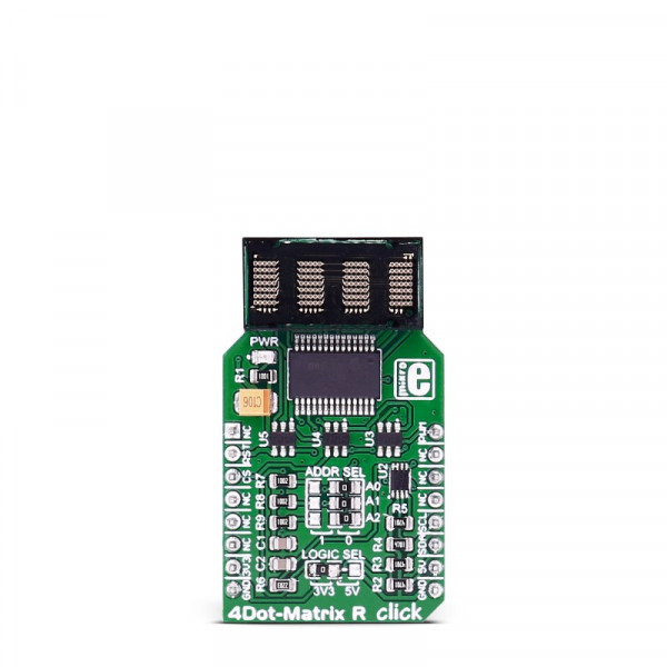
4Dot-Matrix R click


Prices incl. GST
Out of Stock.
- Product Code: MIKROE-2706
- MPN: MIKROE-2706
The display contains all the necessary logic for displaying of characters: integrated ASCII decoder, multiplexer, and drivers make the operation simple and straight-forward. The blanking pin allows a display to be turned off completely or dimmed by applying a PWM signal to this pin. To allow control by using a low pin count, the Click board™ is equipped with the additional circuitry, consisting of an I2C port expander, offering control by only two pins, via the mikroBUS™ I2C interface. These features allow simple and fast development of various applications, which require displaying of characters, numbers, or both.
HOW DOES IT WORK?
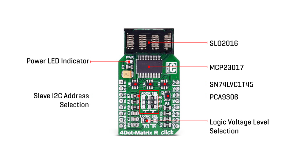
4Dot-Matrix R click uses the SLO2016, 4-Digit 5x7 dot matrix alphanumeric Intelligent Display® device with the integrated memory, ASCII decoder, and driver sections, from Osram. This allows a high autonomy of the module, without any type of display refresh or multiplexing within the application. The character selection is easy, and it is done via the parallel interface, asynchronously. The logic states on seven data pins (D0 to D6) are translated into seven characters selection bits, with two additional pins, used to select the display position of the character (A0 to A1). There are four possible position selections in total, starting with the position 0 at the rightmost position.
The display module contains internal memory with 128 ASCII characters. It contains some special characters too, including letters for English, German, Italian, Swedish, Danish, and Norwegian languages, as well as some other special characters and symbols. The internal character memory cannot be altered, it is read-only. A character which is once selected and displayed at the specific position will remain lit, as long as there is a power supply, or unless it is blanked out or changed. The module itself operates at 5V.
To provide the top performance, each module is tested and subjected to the burn-in procedure. A special care is taken by the manufacturer for each pixel to be displayed equally bright and clear. The display is robust and can sustain a significant electrostatic discharge (ESD). However, a care should be taken when working with the device, since not all the components are ESD resistant.
The parallel data interface is coupled with the MCP23017, a 16-bit I/O expander with I2C interface, from Microchip. This device allows using only two pins (I2S Clock and I2S Data) to control all seven data bits and two more position bits. The expander pins on the B port are used as the character selection pins, while two pins from the A port of the expander are used as the positional data pins. The rest of the control lines, such as the #BL (display blanking), #WR (write enable), and #CLR (memory clear) are routed to the mikroBUS™ PWM, CS, and RST pins, respectively.
Applying a PWM signal to the #BL pin of the display module will allow dimming of the display, depending on the duty cycle of the input signal. To completely dim the display, the BL pin needs to be pulled to a LOW logic level. It is also possible to dim the display by displaying the blank characters. The recommended frequency when using the PWM dimming function is 2.5 kHz and above.
The I2C address of the port expander can be selected by switching three onboard SMD jumpers, labeled as ADDR SEL. These jumpers define the least significant bits of the I2C address, so more than one device can be used on the same I2C bus. Besides the I2C address, it is possible to select the communication voltage level, by switching the SMD jumper labeled as the LOGIC SEL. For this purpose, four-level shifting ICs are employed, of which three are labeled as SN74LVC1T45, single-bit dual-supply bus transceivers, and one for the I2C signal, labeled as the PCA9306, a dual bidirectional I2C bus voltage translator, both from Texas Instruments. These ICs allow simple and reliable bit level shifting functions, by utilizing two different reference voltages to which the logic levels are translated. This allows the Click board™ to be interfaced with both 3.3V and 5V MCUs.
SPECIFICATIONS
| Type | LED Matrix |
| Applications | 4Dot-Matrix R click allows simple and fast development of various applications, which require displaying of characters, numbers, or both |
| On-board modules | SLO2016, a 5x7 dot matrix display from Osram, MCP23017, a 16-bit I/O expander with I2C Interface, from Microchip; SN74LVC1T45, single-bit dual-supply bus transceivers, PCA9306, a dual bidirectional I2C bus voltage translator, both from Texas Instruments |
| Key Features | Four-digit 5x7 dot matrix display with dense and brightly lit pixel elements readable from up to eight feet (2.5m), special characters for several different languages, integrated display and character logic circuitry, and more |
| Interface | I2C |
| Click board size | M (42.9 x 25.4 mm) |
| Input Voltage | 3.3V,5V |
PINOUT DIAGRAM
This table shows how the pinout on 4Dot-Matrix R click corresponds to the pinout on the mikroBUS™ socket (the latter shown in the two middle columns).
| Notes | Pin | Pin | Notes | ||||
|---|---|---|---|---|---|---|---|
| NC | 1 | AN | PWM | 16 | PWM | Display blanking | |
| Clear module RAM | RST | 2 | RST | INT | 15 | NC | |
| NC | 3 | CS | TX | 14 | NC | ||
| NC | 4 | SCK | RX | 13 | NC | ||
| NC | 5 | MISO | SCL | 12 | SCL | I2C clock | |
| NC | 6 | MOSI | SDA | 11 | SDA | I2C data | |
| Power supply | +3.3V | 7 | 3.3V | 5V | 10 | +5V | Power supply |
| Ground | GND | 8 | GND | GND | 9 | GND | Ground |
JUMPERS AND SETTINGS
| Designator | Name | Default | Description |
|---|---|---|---|
| A0 - A2 | ADDR SEL | Right | I2C address LSB selection: left position 0, right position 1 |
| LOGIC SEL | LOGIC SEL | Left | Logic voltage level selection: left position 3.3V, right position 5V |
4Dot-Matrix R click features a jumper for setting the voltage logic level. By default, it's soldered to a 5V position.
SOFTWARE SUPPORT
We provide a demo application for 4Dot-Matrix R click on our Libstock page, as well as a demo application (example), developed using MikroElektronika compilers. The demo can run on all the main MikroElektronika development boards.
Library Description
This library contains functionalities for initializing 4DotMatrix click and communication with it. Communication is done with an MCP23017 16 bit I/O expander via I2C interface. MCP23017 directly communicates with an SLx2016 display to show the characters. All the functions work in a similar fashion, in that they send a character, or several of them, to be displayed. It is possible to send single characters on any of the four display positions, a string of characters, or integers in any numeral system. C4DOT_BL_PIN should be either set to high or should be connected to a PWM module, in which case it would be possible to blink the display or change its intensity.
Key functions:
void c4dot_init();- Initialize the click by setting mBUS pin to appropriate logic levels.void c4dot_writeChar(uint8_t charNum, uint8_t charValue);- Writes charValue to the character on the position of charNum.c4dot_writeText(uint8_t *textToWrite);- Writes up to four characters from textToWrite to the display characters
Example description
The application is composed of three sections:
- System Initialization - GPIO and I2C module initialization
- Application Initialization - Click driver init and setting mBus pins to appropriate logic levels
- Application Task - (code snippet) - text MikroElektronika slides from left to right and the numbers from -20 to 20 are displayed on 4 Dot Matrix click
void applicationTask()
{
// Slide some text in from the right.
for (i = 0; i < 21; i++)
{
c4dot_writeText(text + i);
Delay_ms(150);
}
// Clear and delay.
c4dot_clearDisplay();
Delay_ms(500);
// Write some numbers on the display.
for (i = -20; i <= 20; i++)
{
c4dot_writeIntDec(i);
Delay_ms(150);
}
// Clear and delay.
c4dot_clearDisplay();
Delay_ms(500);
}
The full application code, and ready to use projects can be found on our Libstock page.
Other MikroElektronika libraries used in the example:
- I2C
ADDITIONAL NOTES AND INFORMATION
Depending on the development board you are using, you may need USB UART click, USB UART 2 click or RS232 click to connect to your PC, for development systems with no UART to USB interface available on the board. The terminal available in all MikroElektronika compilers, or any other terminal application of your choice, can be used to read the message.
MIKROSDK
This click board is supported with mikroSDK - MikroElektronika Software Development Kit. To ensure proper operation of mikroSDK compliant click board demo applications, mikroSDK should be downloaded from the LibStock and installed for the compiler you are using.
- Do you have any questions concerning this product?
- mikroBUS™ Standard specification
- LibStock: mikroSDK
- 4Dot-Matrix R click example on Libstock
- 4Dot-Matrix R click schematic
- MCP23017 datasheet
- SLO2016 datasheet
- 4Dot-Matrix R click 2D and 3D files
- Click Boards™ Catalog
- Further products by MikroElektronika