Prices incl. GST
Ready to ship today,
Delivery time appr. 1-3 workdays.
2 in stock
- Product Code: MIKROE-1370
- MPN: MIKROE-1370
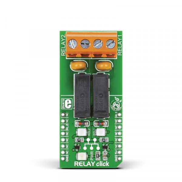
RELAY click can control various devices with up to 5A, 250V AC/30V DC loads. It features two G6D1AASI-5DC power PCB relay modules. The click is designed to run on 5V power supply only. RELAY click communicates with the target microcontroller via mikroBUS™ PWM (RL1) and CS (RL2) pins.
RELAY click is a compact and easy solution for adding a relay to your design. The two screw terminals onboard allow seamless connectivity.
 DO NOT TOUCH THE BOARD WHILE THE EXTERNAL POWER SUPPLY IS ON!
Note: RELAY click has exposed pins/pads. To stay safe take precaution when applying high voltage to the click. The click is to be used by trained personnel only when applying high voltage.
G6D1AASI-5DC power PCB relay
The maximum contact resistance of the G6D1AASI-5DC relay is 100 mΩ.
Communication lines
Communication lines voltage level can be in range between 3.3V and 5V. On-board transistors are used to drive relays by current sinking.
Relay information
A relay is an electrical switch used to terminate or establish a circuit using a low power signal from a microcontroller. It provides complete electrical isolation between microcontroller and controlled circuits. Use the RELAY click™ board with its two G6D1AASI-5DC relays to control various devices with up to 5A, 250V AC/30V DC loads.
Key features
- On-board screw terminals
- G6D1AASI-5DC power PCB relay
- Contact resistance: 100 mΩ max.
- Max. switching voltage 250 VAC, 30 VDC
- Max. switching current 5 A
- Interface: PWM and CS pins
- 5V power supply
Specification
| Type | Relay |
| Applications | Board can be used for turning on/off lights, motors and other high power consumers within the maximum supported voltage/current levels |
| On-board modules | G6D1AASI-5DC power PCB relay |
| Key Features | Control up to 5A, 250V AC/30V DC loads |
| Key Benefits | Screw terminals allow seamless connectivity |
| Interface | GPIO |
| Input Voltage | 5V,5V |
| Compatibility | mikroBUS |
| Click board size | L (57.15 x 25.4 mm) |
Pinout diagram
This table shows how the pinout on RELAY click corresponds to the pinout on the mikroBUS™ socket (the latter shown in the two middle columns).
Programming
Code examples that demonstrate the usage of RELAY click with MikroElektronika hardware, written for mikroC for ARM, AVR, PIC and PIC32 are available on Libstock.
The following code snippet is a simple example of RELAY click toggled with buttons on an EasyPIC v7.
 1 sbit Relay1           at  LATC1_bit;
2 sbit Relay2           at  LATE0_bit;
3 sbit Relay1_Direction at TRISC1_bit;
4 sbit Relay2_Direction at TRISE0_bit;
5 void main()
6 {
7     Relay1_Direction = 0;                      // Set relay direction as output
8     Relay2_Direction = 0;                      // Set relay direction as output
9     Relay1 = 0;                                // Turn off relay1
10     Relay2 = 0;                                // Turn off relay2
11
12     while( 1 )
13     {
14         if( Button( &PORTB, 0, 80, 1 ) )       // Toggle relay 1 on B0 button press
15             Relay1 = ~Relay1;
16
17         if( Button( &PORTB, 1, 80, 1 ) )       // Toggle relay 2 on B1 button press
18             Relay2 = ~Realy2;
19     }
20 } 


