Prices incl. GST
Out of Stock.
- Product Code: MIKROE-2396
- MPN: MIKROE-2396
The analog output is fed through a 12-bit ADC with the final output going through the mikroBUS™ SPI interface.
Since the ADC has a limited min-max range (0-2043), R Meter click employs a multiplexer that can adjust the input signal to the amplifier and thus allow the same ADC to measure four different scopes of values (0-1k , 1k-100k, 100k-1M)
The supplied firmware (available on Libstock) automatically scans the ADC value and switches the multiplexer output based on the resistor in place. The multiplexer interfaces directly with the target board MCU through mikroBUS™ S1, S2, and S3 pins (in place of default mikroBUS™ PWM, INT and RST).
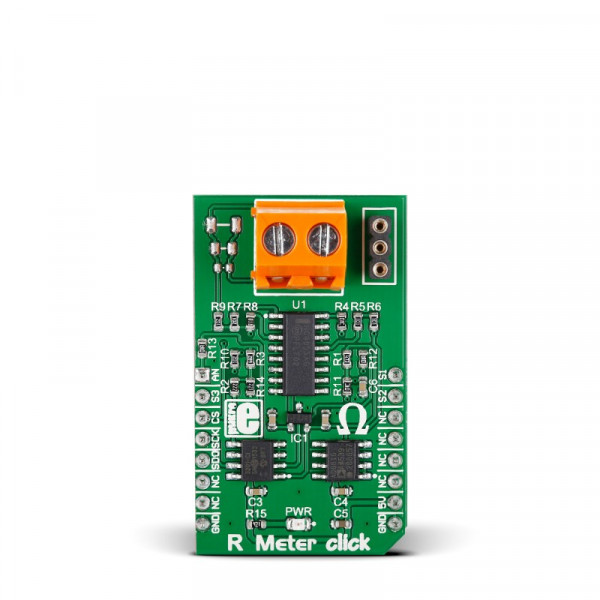
Onboard screw terminals are placed to allow the click to be used with multimeter probes.
The board is designed to use a 5V power supply.
Specification
| Type | Measurements |
| Applications | Measuring value of resistors |
| On-board modules | 12-bit ADC |
| Key Features | Three plates for SMD resistors and header for thru hole resistors, Non-inverting amplifier circuit |
| Key Benefits | Screw terminals for multimeter probes |
| Interface | SPI,Analog,GPIO |
| Input Voltage | 5V,5V |
| Compatibility | mikroBUS |
| Click board size | M (42.9 x 25.4 mm) |
R Meter click is a mikroBUS™ add-on board with circuitry for measuring the value of resistors. The board can be used to measure a wide range of resistors (from 0 to 1 Mega Ohm). It has three plates for SMD resistors (0603, 0805, 1206) and a header for thru hole resistors.
Features and usage notes
R Meter click is a handy tool but it’s not to be used as a precision instrument. The linearity of the OpAmp impacts the measurement.
The board is designed to use a 5V power supply.
Programming
This example shows how to set up R Meter click, and read out the resistance in ohms (Ω) every 250 ms.
1 #include2 #include "r_meter.h" 3 4 //sbits 5 sbit S1 at GPIOA_ODR.B0; 6 sbit S2 at GPIOD_ODR.B10; 7 sbit S3 at GPIOC_ODR.B2; 8 sbit R_METER_CS at GPIOD_ODR.B13; 9 10 //Prototypes 11 void system_setup( void ); 12 13 //Main 14 void main() 15 { 16 //Local Declarations 17 char txt[20] = { 0 }; 18 float ohms_var = 0; 19 20 //Setup 21 system_setup(); 22 23 while (1) 24 { 25 ohms_var = r_meter_get_ohms(); 26 if( ohms_var == 0 ) 27 UART1_Write_Text( "Over Rangern" ); 28 else 29 { 30 FloatToStr( ohms_var, txt ); 31 UART1_Write_Text( "OHMS: " ); 32 UART1_Write_Text( txt ); 33 UART1_Write_Text( "rn" ); 34 } 35 delay_ms(250); 36 } 37 } 38 39 void system_setup( void ) 40 { 41 42 // GPIOs 43 GPIO_Digital_Output( &GPIOD_BASE, _GPIO_PINMASK_10 | _GPIO_PINMASK_13 ); 44 GPIO_Digital_Output( &GPIOC_BASE, _GPIO_PINMASK_2 ); 45 GPIO_Digital_Output( &GPIOA_BASE, _GPIO_PINMASK_0 ); 46 GPIO_Digital_Input( &GPIOA_BASE, _GPIO_PINMASK_4 ); 47 48 //UART 49 UART1_Init(9600); // Initialize UART module at 9600 bps 50 Delay_ms(100); // Wait for UART module to stabilize 51 UART1_Write_Text( "Startingrn" ); 52 53 //ADC 54 //ADC1_Init(); //For direct analog values 55 Delay_ms(200); 56 UART1_Write_Text( "UART Initializedrn" ); 57 SPI3_Init_Advanced( _SPI_FPCLK_DIV4, 58 _SPI_MASTER | _SPI_8_BIT | _SPI_CLK_IDLE_LOW | 59 _SPI_SECOND_CLK_EDGE_TRANSITION | _SPI_MSB_FIRST | 60 _SPI_SS_DISABLE | _SPI_SSM_ENABLE | 61 _SPI_SSI_1, 62 &_GPIO_MODULE_SPI3_PC10_11_12 ); 63 64 Delay_ms( 200 ); 65 UART1_Write_Text( "SPI Initializedrn" ); 66 67 r_meter_init(); 68 UART1_Write_Text( "R Meter Initializedrn" ); 69 }
Code examples that demonstrate the usage of R Meter click with MikroElektronika hardware, written for mikroC for ARM, AVR, dsPIC, FT90x, PIC and PIC32 are available on Libstock.


