
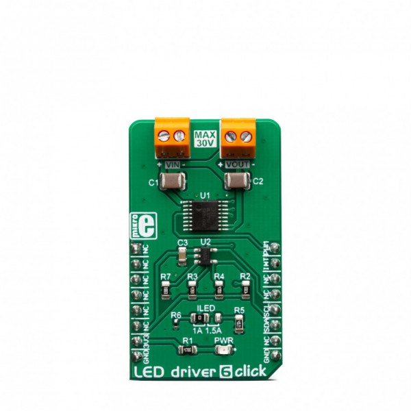
LED driver 6 Click


Prices incl. GST
Out of Stock.
- Product Code: MIKROE-3400
- MPN: MIKROE-3400
The AL1781 integrates a low-side current sink which allow LED strips or LED bulbs to be connected in the common-anode topology for increased effectiveness and power optimization. This IC is designed with the power optimization in mind: whenever there is no valid PWM signal on its input pin, it enters the low-power mode, preventing unnecessary power dissipation. An additional ADC IC is used, allowing advanced power optimization. Offering good reliability, linear dimming response, and low power consumption, LED driver 6 click is a perfect solution for smart lighting applications, SCL LED bulbs, but also for driving LED strips and high-power LEDs.
How does it work?
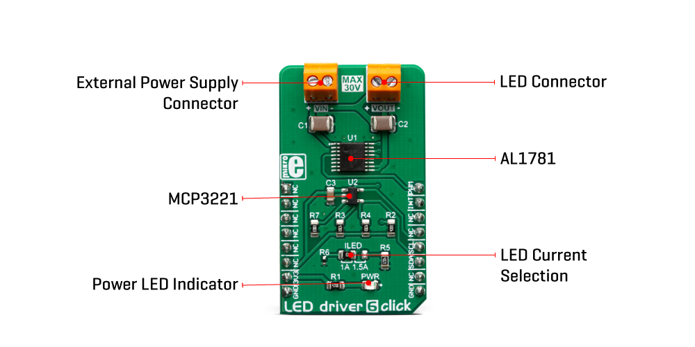
LED driver 6 click is based on the AL1781, a single-channel PWM dimmable linear LED driver by Diodes Incorporated. It is a constant-current driver, which can sink up to 1500mA. It has a low-side current sink which allow LED strips or LED bulbs to be connected in the common-anode topology for increased effectiveness and power optimization. The constant current through the connected LED can be selected by a SMD jumper labeled as ILED, between two values: 1A and 1.5A.
The AL1781 IC can be operated with a PWM signal in the frequency range from 1kHz to 40kHz. By applying the PWM signal with the duty cycle of less than 4ms, it is possible to tune the light intensity of the connected LED light element. A LOW pulse width of more than 4ms will set the device into the low-power mode (suspend). The lowest light intensity that can be reached by applying the PWM frequency of 1kHz is 0.1%, while 40kHz allows the lowest brightness level of 4% of the full light intensity. A High PWM frequency allows for less visible flickering, but limits the lowest light intensity level, at the same time. PWM1 and PWM2 pins of the AL1781 are routed to the mikroBUS™ PWM and CS pins and are labeled as PW1 and PW2.
Adaptive Thermal Management (ATM) scheme is one of the key features of the AL1781. It can be used to optimize the power consumption by adjusting the voltage of the external power supply unit (PSU): the excessive voltage applied to the connected LED will be dissipated as heat within the AL1781 IC. Therefore, the voltage level of the external PSU should be kept above the forward voltage of the connected LED plus minimum voltage headroom (VF + VLED_REG). The ATM injects current through the LEDPG pin of the AL1781. This current is converted to a voltage level, and it is sampled by the MCP3221, a low-power 12-bit A/D converter with I2C interface, by Microchip. It has its I2C pins routed to the respective mikroBUS™ I2C pins, allowing the host MCU to read the LEDPG voltage and make PSU voltage adjustments. Please note that if an external PSU with no external regulation is used, its voltage should stay within the mentioned range (VF of the connected LED element + VLEDx_REG as per AL1781 datasheet). However, the voltage should always stay below 30V.
The AL1781 IC also integrates an abundance of protection features for increased reliability: undervoltage, open or short circuit at the output, and thermal protection. If any of these protections become activated, a fault event will be reported on a dedicated pin, labeled as FAULTB. This pin is routed to the mikroBUS™ INT pin and it is asserted to a LOW logic level when a fault event occurs.
Deep Dimming Capability helps with power efficiency. Subjective perception of the light intensity differs from the measured light. For example, the light intensity of 10% (in respect to the applied duty cycle) is perceived as 32% of the full light intensity. Deep Dimming Capability helps with energy saving, providing an optimal light output. Deep Dimming down to 0.1% is possible with the AL1781 IC, since it can be operated with the pulse width as low as 1 µS, while still providing good linearity.
LED driver 6 click is designed to be used along with an external PSU and an MCU. The full potential of the LED driver 6 click is achieved when combined with a dedicated ambient light sensing Click board™ such asAmbient 5 click: by receiving information about the ambient light intensity from Ambient 5 click, the MCU can generate PWM signal in respect to the required intensity tuning and send it to LED driver 6 click to regulate the intensity of the ambient lighting.
This Click Board™ is designed to be operated by 3.3V logic levels only. A proper logic voltage level translation should be performed before the Click board™ is used MCUs which are operated at 5V.
Specifications
| Type | Buck |
| Applications | LED driver 6 click is a perfect solution for smart lighting applications, SCL LED bulbs, but also for driving LED strips and high-power LEDs. |
| On-board modules | AL1781, a single-channel PWM dimmable linear LED driver by Diodes Incorporated; MCP3221, a low-power 12-bit A/D converter with I2C interface, by Microchip. |
| Key Features | Many protection features for increased reliability: undervoltage, open or short circuit at the output, thermal protection… High-frequency E-flicker free technology with Deep Dimming capability, Adaptive Thermal Management scheme, etc. |
| Interface | I2C,PWM |
| Input Voltage | 3.3V |
| Click board size | M (42.9 x 25.4 mm) |
Pinout Diagram
This table shows how the pinout on LED Driver 6 Click corresponds to the pinout on the mikroBUS™ socket (the latter shown in the two middle columns).
| Notes | Pin | Pin | Notes | ||||
|---|---|---|---|---|---|---|---|
| NC | 1 | AN | PWM | 16 | PW1 | PWM Input 1 | |
| NC | 2 | RST | INT | 15 | INT | Fault status | |
| NC | 3 | CS | RX | 14 | NC | ||
| NC | 4 | SCK | TX | 13 | NC | ||
| NC | 5 | MISO | SCL | 12 | SCL | I2C Clock | |
| NC | 6 | MOSI | SDA | 11 | SDA | I2C Data | |
| Power Supply | 3.3V | 7 | 3.3V | 5V | 10 | NC | |
| Ground | GND | 8 | GND | GND | 9 | GND | Ground |
Onboard Settings And Indicators
| Label | Name | Default | Description |
|---|---|---|---|
| PWR | PWR | - | Power LED indicator |
| VOUT | VOUT | - | LED connector |
| VIN | VIN | - | External power supply connector |
| JP1 | ILED | Left | LED current selection: left position 1A, right position 1.5A |
Software Support
We provide a library for the LED Driver 6 Click on our LibStock page, as well as a demo application (example), developed using MikroElektronika compilers. The demo can run on all the main MikroElektronika development boards.
Library Description
Library provides full control of the LEDs illumination. PWM functions are used to control the brightness temperature of the LEDs. The library also offers reading the current PG voltage score that serves to regulate lights and alerts.
Key functions:
uint16_t leddriver6_getPGVoltage()- Reads PG output voltageuint32_t leddriver6_pwmInit(uint16_t freq)-void leddriver6_pwmSetDuty(uint16_t duty)- PWM set duty cycle
Examples description
The application is composed of the three sections :
- System Initialization - Initialization I2C module, sets INT pin as INPUT and PWM pin as OUTPUT
- Application Initialization - Initialization driver init and pwm init for LED
- Application Task - Waits for valid user input and executes functions based on set of valid commands
Commands : '+' - Increase LED light '-' - Decrease LED light 'v' - Display current PG voltage
void applicationTask()
{
uint8_t dataReady_;
char receivedData_;
dataReady_ = UART_Rdy_Ptr( );
if (dataReady_ != 0)
{
receivedData_ = UART_Rd_Ptr( );
switch (receivedData_)
{
case '+' :
{
_increase();
break;
}
case '-' :
{
_decrease();
break;
}
case 'v' :
{
_currentPGVoltage();
break;
}
}
}
}
Additional Functions :
void _increase( )- Increase LED's lightvoid _decrease( )- Decrease LED's lightvoid _currentPGVoltage( )- Reads and logs PG voltage
The full application code, and ready to use projects can be found on our LibStock page.
Other mikroE Libraries used in the example:
I2CPWMUART
Additional notes and informations
Depending on the development board you are using, you may need USB UART click, USB UART 2 click or RS232 click to connect to your PC, for development systems with no UART to USB interface available on the board. The terminal available in all MikroElektronika compilers, or any other terminal application of your choice, can be used to read the message.
MIKROSDK
This click board is supported with mikroSDK - MikroElektronika Software Development Kit. To ensure proper operation of mikroSDK compliant click board demo applications, mikroSDK should be downloaded from the LibStock and installed for the compiler you are using.