


Prices incl. GST
Out of Stock.
- Product Code: MIKROE-2036
- MPN: MIKROE-2036
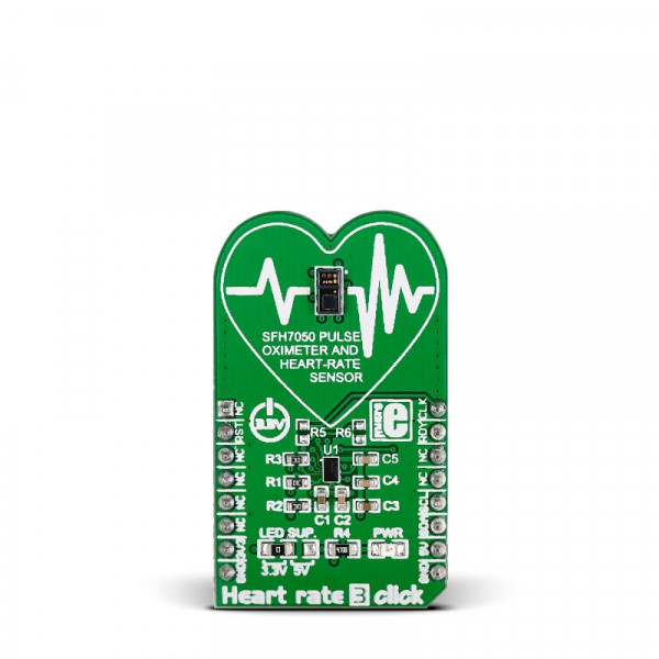
The SFH7050 multichip package contains 3 LEDs and one photodiode separated with a light barrier to prevent optical crosstalk. When the three LEDs shine through a subject’s finger, some of the light is absorbed by the pulsating blood.
The analog reading from the SFH7050 is forwarded to the AFE chip that is able to derive pulse readings from the intensity of the reflected light.
AFE4404 is highly-configurable and adaptable for different usage scenarios (different lighting conditions or skin tones) making Heart rate 3 click a robust heart rate monitoring solution.
The board communicates with the target MCU through the mikroBUS™ I2C interface, with additional functionality provided by RST, CLK and RDY pins.
Heart rate 3 click works on a 3.3V power supply, but an onboard jumper allows you to set the voltage for driving the SFH7050 LEDs at either 3.3V or 5V.
Specification
| Type | Biomedical |
| Applications | Optical heart rate monitoring |
| On-board modules | OSRAM’s SFH7050 pulse oximetry module, heart rate monitoring module, TI AFE4404 (analong-front-end) IC |
| Key Features | TI AFE4404 AFE (analog-front-end) |
| Key Benefits | Separate optical and signal processing circuitry |
| Interface | GPIO,I2C |
| Input Voltage | 3.3V or 5V |
| Compatibility | mikroBUS |
| Click board size | M (42.9 x 25.4 mm) |
Programming
Setting up of Heartrate 3 click and external interrupt to read values at 100hz and using an algorithm to find a heartrate.
1 #include2 #include "heartrate_3.h" 3 #include "resources.h" 4 5 6 // HeartRate 3 GPIO 7 sbit RST at GPIOC_ODR.B2; 8 9 void system_setup( void ); 10 void setup_interrupt(); 11 12 char uart_text[20] = {0}; 13 uint64_t int_count = 0; //Used by timer to calibrate sampling freq. 14 15 void main() 16 { 17 //Local Declarations 18 uint16_t rate = 0; 19 char txt[15] = {0}; 20 21 system_setup(); // GPIO / HeartRate 3 / UART / I2C Setups 22 Delay_ms(200); 23 initStatHRM(); // Initializes values to 0 24 setup_interrupt(); // Setup interrupt handler 25 26 while(1) 27 { 28 rate = hr3_get_heartrate(); 29 30 IntToStr( rate, uart_text ); 31 UART1_Write_Text( uart_text ); 32 UART1_Write_Text( "rn" ); 33 } 34 35 } 36 37 void system_setup( void ) 38 { 39 //Local Declarations 40 char text[40] = { 0 }; 41 dynamic_modes_t dynamic_modes; 42 uint8_t address = 0x58; 43 44 //Set up dynamic modes for Heart Rate 3 Initialization 45 dynamic_modes.transmit = trans_dis; //Transmitter disabled 46 dynamic_modes.curr_range = led_double; //LED range 0 - 100 47 dynamic_modes.adc_power = adc_on; //ADC on 48 dynamic_modes.clk_mode = osc_mode; //Use internal Oscillator 49 dynamic_modes.tia_power = tia_off; //TIA off 50 dynamic_modes.rest_of_adc = rest_of_adc_off; //Rest of ADC off 51 dynamic_modes.afe_rx_mode = afe_rx_normal; //Normal Receiving on AFE 52 dynamic_modes.afe_mode = afe_normal; //Normal AFE functionality 53 54 //GPIO setup 55 GPIO_Digital_Output( &GPIOC_BASE, _GPIO_PINMASK_2 ); 56 GPIO_Digital_Input( &GPIOA_BASE, _GPIO_PINMASK_0 ); 57 GPIO_Digital_Input( &GPIOD_BASE, _GPIO_PINMASK_10 ); 58 59 //UART Initialize 60 UART1_Init( 9600 ); 61 UART1_Write_Text( "UART is Initializedrn" ); 62 63 //Toggle Reset pin 64 RST = 0; 65 Delay_us(50); 66 RST = 1; 67 68 //I2C Initialize 69 I2C1_Init_Advanced( 400000, &_GPIO_MODULE_I2C1_PB67 ); 70 UART1_Write_Text( "I2C Initializedrn" ); 71 72 //Heart Rate 3 Initialize 73 hr3_init( address, &dynamic_modes ); 74 75 76 } 77 78 void setup_interrupt() 79 { 80 GPIO_Digital_Output(&GPIOE_BASE, _GPIO_PINMASK_HIGH); // Enable digital output on PORTD 81 GPIOE_ODR = 0xAAAA; 82 GPIO_Digital_Input(&GPIOD_BASE, _GPIO_PINMASK_10); 83 84 RCC_APB2ENR.AFIOEN = 1; // Enable clock for alternate pin functions 85 AFIO_EXTICR3 = 0x0300; // PD10 as External interrupt 86 EXTI_RTSR = 0x00000400; // Set interrupt on Rising edge 87 EXTI_IMR |= 0x00000400; // Set mask 88 NVIC_IntEnable(IVT_INT_EXTI15_10); // Enable External interrupt 89 EnableInterrupts(); // Enables the processor interrupt. 90 } 91 92 void ExtInt() iv IVT_INT_EXTI15_10 ics ICS_AUTO { 93 EXTI_PR.B10 = 1; // clear flag 94 int_count++; 95 statHRMAlgo( hr3_get_led1_amb1_val() ); // Give led1 ambient value to heartrate function. ( 100 times a second ) 96 97 }
Code examples that demonstrate the usage of Heart rate 3 click with MikroElektronika hardware, written for mikroC for ARM, AVR, dsPIC, FT90x, PIC and PIC32 are available on Libstock