
Compass 2 click


Prices incl. GST
Out of Stock.
- Product Code: MIKROE-2264
- MPN: MIKROE-2264
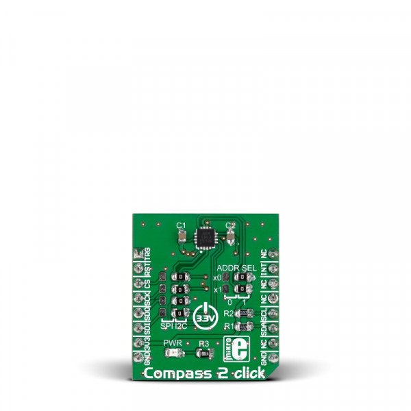
Compass 2 click carries the AK8963 3-axis electronic compass. The AK8963 sensor is based on the Hall effect. The click is designed to run on a 3.3V power supply only. It communicates with the target microcontroller through either I2C or SPI interface, with additional functionality provided by the INT pin on the mikroBUS™ line.
AK8963 features
The built-in ADC converter can be set up at either 14 or 16 bit resolution, for each of the 3 axes. The sensitivity is 0.6µT/LSB typ. at 14-bit, and 0.15µT/LSB at 16-bit.
AK8963 incorporates magnetic sensors for detecting terrestrial magnetism in the X-axis, Y-axis, and Z-axis, a sensor driving circuit, signal amplifier chain, and an arithmetic circuit for processing the signal from each sensor.
Key features
- AK8963 electronic compass
- Built-in ADC converter
- 14-/16-bit selectable resolution
- Sensitivity:
- 0.6 µT/LSB typ. (14-bit)
- 0.15µT/LSB typ. (16-bit)
- I2C or SPI interface
- 3.3V power supply
Specification
| Type | Magnetometer |
| Applications | Position detection, navigation and orientation for portable devices |
| On-board modules | AK8963 3-axis electronic compass |
| Key Features | Sensitivity: 0.6µT/LSB typ. at 14-bit, and 0.15µT/LSB at 16-bit |
| Key Benefits | Selectable interface, Configurable ADC resolution |
| Interface | SPI,GPIO,I2C |
| Input Voltage | 3.3V |
| Compatibility | mikroBUS |
| Click board size | S (28.6 x 25.4 mm) |
Pinout diagram
This table shows how the pinout on Compass 2 click corresponds to the pinout on the mikroBUS™ socket (the latter shown in the two middle columns).
| Notes | Pin | mikroBUStm | Pin | Notes | |||
|---|---|---|---|---|---|---|---|
| External trigger pulse input pin | TRG | 1 | AN | PWM | 16 | NC | Not connected |
| Reset pin | RST | 2 | RST | INT | 15 | INT | Interrupt |
| Chip Select | CS | 3 | CS | TX | 14 | NC | Not connected |
| Serial Clock input pin | SCK | 4 | SCK | RX | 13 | NC | Not connected |
| SPI Master Input Slave Output | MISO | 5 | MISO | SCL | 12 | SCL | I2C Clock |
| SPI Master Output Slave Input | MOSI | 6 | MOSI | SDA | 11 | SDA | I2C Data |
| Power supply | +3.3V | 7 | 3.3V | 5V | 10 | NC | Not connected |
| Ground | GND | 8 | GND | GND | 9 | GND | Ground |
Features and usage notes
The AK8964 has several operating modes which can be configured by setting a specific register (CNTL1) to certain values. The following is a list of available operating modes with partial descriptions (to give you an overview). The configuration details are available on page 13 of the official data sheet, while the complete descriptions
(1) Power-down mode
Power to almost all internal circuits is turned off. All registers are accessible in power-down mode. However, fuse ROM data cannot be read correctly. Data stored in read/write registers are remained. They can be reset by soft reset.
(2) Single measurement mode
When single measurement mode (MODE[3:0]=“0001”) is set, sensor is measured, and after sensor measurement and signal processing is finished, measurement data is stored to measurement data registers (HXL to HZH), then AK8963 transits to power-down mode automatically.
(3) Continuous measurement mode 1 and 2
When continuous measurement mode 1 (MODE[3:0]=“0010”) or 2 (MODE[3:0]=“0110”) is set, sensor is measured periodically at 8Hz or 100Hz respectively. When sensor measurement and signal processing is finished, measurement data is stored to measurement data registers (HXL ~ HZH) and all circuits except for the minimum circuit required for counting cycle lentgh are turned off (PD).
(4) External trigger measurement mode
When external trigger measurement mode (MODE[3:0]=“0100”) is set, AK8963 waits for trigger input. When a pulse is input from TRG pin, sensor measurement is started on the rising edge of TRG pin. When sensor measurement and signal processing is finished, measurement data is stored to measurement data registers (HXL to HZH) and all circuits except for the minimum circuit required for trigger input waiting are turned off (PD state).
(4) External trigger measurement mode
Fuse ROM access mode is used to read Fuse ROM data. Sensitivity adjustments for each axis is stored in fuse ROM.
Compass 2 click has both SPI and I2C interfaces. The active interface is configured with onboard jumpers. If you use I2C, an additional jumper will allow you to set the I2C address.
Programming
This code snippet initiates Compass 2 with I2C communication, and reads out the heading value, along with a direction, ( N, NE, E, etc ) from the module to a UART terminal every 100 ms.
1 #include2 #include "compass2_hw.h" 3 4 sbit COMPASS2_CS at GPIOD_ODR.B13; 5 6 void system_setup( bus_mode_t mode, uint8_t addr ); 7 8 float mRes; // scale resolutions per LSB for the sensors 9 uint8_t asax, asay, asaz; 10 float adjusted_ASAX, adjusted_ASAY, adjusted_ASAZ; 11 float heading, adjusted_MX, adjusted_MY, adjusted_MZ, magbias[3]; 12 int16_t mx, my, mz; 13 char text[20] = { 0 }; 14 15 void main() 16 { 17 // Local Declarations 18 uint8_t address = 0x0F; 19 bus_mode_t my_mode = I2C; 20 float heading = 0; 21 char uart_text[5] = { 0 }; 22 23 system_setup( my_mode, address ); 24 25 while(1) 26 { 27 compass2_get_all_values( &mx, &my, &mz ); 28 heading = compass2_get_compass_heading( mx, my, mz ); 29 30 if( heading < 0 ) 31 heading += 360; 32 33 UART1_Write_Text( "Heading: " ); 34 FloatToStr( heading, text ); 35 UART1_Write_Text( text ); 36 UART1_Write_Text( " Direction: " ); 37 38 if( heading >= 330 || heading <= 30 ) 39 { 40 uart_text[0] = 'N'; 41 uart_text[1] = 'n'; 42 } 43 else if( heading >= 300 && heading <= 330 ) 44 { 45 uart_text[0] = 'N'; 46 uart_text[1] = 'W'; 47 uart_text[2] = 'n'; 48 } 49 else if( heading >= 240 && heading <= 300) 50 { 51 uart_text[0] = 'W'; 52 uart_text[1] = 'n'; 53 } 54 else if( heading >= 210 && heading <= 240 ) 55 { 56 uart_text[0] = 'S'; 57 uart_text[1] = 'W'; 58 uart_text[2] = 'n'; 59 } 60 else if( heading <= 210 && heading >= 150 ) 61 { 62 uart_text[0] = 'S'; 63 uart_text[1] = 'n'; 64 } 65 else if( heading <= 150 && heading >= 120 ) 66 { 67 uart_text[0] = 'S'; 68 uart_text[1] = 'E'; 69 uart_text[2] = 'n'; 70 } 71 else if( heading <= 120 && heading >= 60 ) 72 { 73 uart_text[0] = 'E'; 74 uart_text[1] = 'n'; 75 } 76 else if( heading <= 60 && heading >= 30 ) 77 { 78 uart_text[0] = 'N'; 79 uart_text[1] = 'E'; 80 uart_text[2] = 'n'; 81 } 82 83 UART1_Write_Text( uart_text ); 84 UART1_Write_Text( "rn" ); 85 86 Delay_ms(100); 87 } 88 89 } 90 91 void system_setup( bus_mode_t mode, uint8_t addr ) 92 { 93 // GPIOs 94 GPIO_Digital_Output( &GPIOB_BASE, _GPIO_PINMASK_13 ); 95 96 // UART 97 UART1_Init( 9600 ); 98 UART1_Write_Text( "UART Initializedrn" ); 99 100 // I2C 101 I2C1_Init_Advanced( 100000, &_GPIO_MODULE_I2C1_PB67 ); 102 UART1_Write_Text( "I2C Initializedrn" ); 103 104 // Compass 2 105 UART1_Write_Text( "Getting Device ID..." ); 106 compass2_hw_init( addr, mode ); 107 UART1_Write_Text( "Compass Initializedrn" ); 108 109 // Compass 2 setup 110 mRes = compass2_set_scale_factor( RES_16 ); 111 magbias[0] = +470; 112 magbias[1] = +120; 113 magbias[2] = +125; 114 115 compass2_get_self_test( &mx, &my, &mz ); 116 UART1_Write_Text( "x y z Values: " ); 117 LongWordToStr( mx, text ); 118 UART1_Write_Text( text ); 119 UART1_Write_Text( "t" ); 120 LongWordToStr( my, text ); 121 UART1_Write_Text( text ); 122 UART1_Write_Text( "t" ); 123 LongWordToStr( mz, text ); 124 UART1_Write_Text( text ); 125 UART1_Write_Text( "rn" ); 126 127 compass2_get_adjustment( &asax, &asay, &asaz ); 128 adjusted_ASAX = ( (float)asax - 128 ) / 256 + 1; 129 adjusted_ASAY = ( (float)asay - 128 ) / 256 + 1; 130 adjusted_ASAZ = ( (float)asaz - 128 ) / 256 + 1; 131 132 compass2_set_mode( MODE_CONT_1 ); 133 compass2_set_scale_factor( RES_16 ); 134 135 UART1_Write_Text( "Compass2 Setup Completed..rn" ); 136 }
Code examples that demonstrate the usage of Compass 2 click with MikroElektronika hardware, written for mikroC for ARM, AVR, dsPIC, FT90x, PIC and PIC32 are available on Libstock