
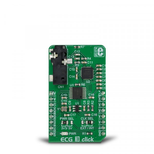
ECG 3 Click


Prices incl. GST
Out of Stock.
- Product Code: MIKROE-3273
- MPN: MIKROE-3273
A high DC offset range allows it to be used with various electrodes, while the interrupt-based heart rate detection eliminates the need for the detection algorithm on the host MCU. A very high input impedance, coupled with the low-pass and high-pass filter options, allows user-adjustable tolerance vs accuracy factor. Embedded R-to-R detection and ECG functionalities simplify the firmware development.
The inputs of the biopotential channel of the MAX30003 AFE IC are protected against the electrostatic discharge (ESD) and filtered against electromagnetic interferences (EMI), primarily generated by AC mains. Sequential power-up procedure reduces the inrush current through the electrodes, while fast recovery combined with the DC coupling helps to handle large voltage offsets between electrodes after the electrosurgery or defibrillation conditions occur.
Note: ECG 3 is a development and prototyping tool. It is not intended to be used for a medical treatment of patients and other life-critical applications!
How does it work?
ECG 3 click is equipped with the MAX30003 IC, an ultra-low power, single channel, integrated biopotential AFE, with the ECG and R-to-R detection functionality, from Maxim Integrated. To better understand the working principles of the ECG 3 click, some knowledge about how the heart works is required. There is a useful learning article about ECG monitoring, which can be a good starting point.
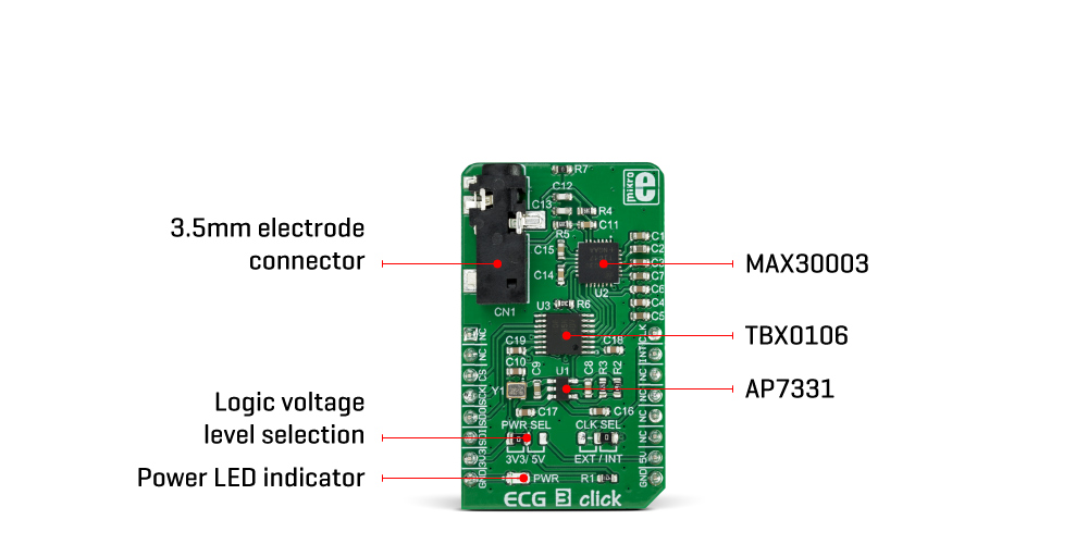
Electrocardiography is the process of recording the electrical activity of the heart over a period of time, using electrodes placed on the body. These electrodes detect the small electrical changes that arise from the electrophysiological pattern of the heart muscle. ECG 3 click is used to record a single-channel electrocardiogram. The electrodes can be attached to the ECG 3 click via the 3.5mm jack. The ECG 3 uses the three-electrode system, where two electrodes are connected to the positive and negative end of the differential input of the MAX30003 (ECGP and ECGN pins), while the third electrode is connected to the GND. The Click board™ can be used with the cable and electrodes such as these: ECG/EMG cable, and ECG/EMG electrodes. In this case, the white electrode is the GND electrode.
These voltage impulses are weak by nature and in the range of just a few millivolts. Therefore, any interferences might obscure them, making them undetectable. These interferences might be induced in the human body itself, or they might appear as the result of the activity of other muscles, such as skeletal muscles. The MAX30003 is armed with several methods to reduce these interferences. However, the placement of the measurement electrodes is also crucial for the accurate readings. More about the electrodes and their placement can be found in the aforementioned learning article.
The MAX30003 IC has two differential inputs which comprise a single ECG channel. Therefore, the heart can be monitored from a single plane only - the coronal plane. However, this is quite enough for the fitness, heart rate monitoring and similar applications. All the mentioned features are mostly related to the conditioning of the input signal and protecting the IC from voltage surges, so several types of electrodes can be used. The inputs are equipped with a single-pole, high-pass (HP) EMI filter, with the cutoff frequency set to 2MHz, as the first line of defense against the interferences. A set of integrated clamping diodes prevent the ESD surges to reach the IC and damage it. The inputs are connected with the electrodes over the protective serial switches, which are disabled by default. When developing own application, a care should be taken to turn these switches ON. However, the mikroSDK library functions included with the Click board™ take care about the proper configuring and initialization.
The differential inputs are further amplified by an integrated low-noise, high-impedance instrumentation amplifier (IA) with the fixed gain. The IA section features yet another HP filter which helps to reject movement artifacts, which are generated by skeletal muscles. Depending on the application requirements, higher cutoff frequency will result with less accurate ECG signal, but the effects of the motion artifacts will be reduced even more. This frequency is determined by a capacitor between CAPP and CAPN pins of the MAX30003 IC, which is about 0.04Hz with the 1uF capacitor used on the ECG 3 click. The recommended range for the HP cutoff frequency is from 0.04Hz up to 4.4Hz.
Following the IA section, the MAX30003 incorporates the two-pole low-pass anti-aliasing (LP) filter, with the cutoff frequency at 600Hz, which ensures good sampling quality. The programmable gain amplifier is the next section in the signal chain, allowing optimal signal amplitudes to reach the next stage - the sigma-delta 18-bit A/D converter, which ultimately generates the heart rate readings over the SPI interface.
Other features of the MAX30003 IC include the self-testing programmable voltage sources and no leads detection. One of the key features of the AFE is the R - R interval detection. R-wave is a part of the heart rate signal, which has the highest peak. The distance between the two peaks is closely related to the heart rate and can give a good insight into the shape of the R-wave when no plot is available. Closely matched R - R and BPM values indicate that R waves are quite sharp, without irregularities. Also, the BMP (beats per minute) is an average value, while the R - R interval represents the timing between two peaks.
The extensive interrupt engine can be used to trigger the host MCU from various sources, including interrupt events due to lead detection, R-R detection, fast-recovery event, FIFO buffer states, and many more. These interrupt sources can be utilized to trigger a state change on the interrupt pin (INTB) of the MAX30003 IC. This pin is active-low.
The MAX30003 IC requires a clock signal, which is provided by the onboard oscillator. The frequency of the oscillator is 32.768 kHz. However, the Click board™ accepts the external clock signal, over the PWM pin of the mikroBUS™, which is labeled as CLK. Regarding the voltage levels, there is a TXB0106 IC implemented on the ECG 3 click, allowing it to operate with both 3.3V and 5V MCUs. This IC is a bi-directional voltage level translator from Texas Instruments. It is a proven solution used on many different Click board™ designs, which transforms voltages of the logic signals (SPI, interrupt, clock) to 1.8V-level signals, which is acceptable for the MAX30003 IC. This allows many different MCUs to be interfaced with the ECG 3 click The logic voltage selection can be done with the onboard SMD jumper labeled as PWR SEL, while the clock source can be selected by another SMD jumper, labeled as CLK SEL.
Specifications
| Type | Biomedical |
| Applications | ECG 3 click is an ideal solution for development of heart rate monitoring applications, fitness applications, for the ECG bio-authentication, and similar applications |
| On-board modules | MAX30003, an ultra-low power, single channel, integrated biopotential AFE, with the ECG and R - R detection, from Maxim Integrated; TBX0106, a bidirectional level translator from Texas Instruments, AP7331, a low dropout linear regulator from Diodes Incorporated |
| Key Features | Input ESD and EMI protection, high input impedance allows various electrodes to be used, a very large common mode rejection rate of over 100 dB (CMRR), signal conditioning reduces influence of movement artifacts, can be interfaced with both 3.3V and 5V MCUs |
| Interface | SPI |
| Input Voltage | 3.3V,5V |
| Click board size | M (42.9 x 25.4 mm) |
Pinout diagram
This table shows how the pinout on ECG 3 Click corresponds to the pinout on the mikroBUS™ socket (the latter shown in the two middle columns).
| Notes | Pin | Pin | Notes | ||||
|---|---|---|---|---|---|---|---|
| NC | 1 | AN | PWM | 16 | CLK | External clock | |
| NC | 2 | RST | INT | 15 | INT | Interrupt | |
| SPI chip Select | CS | 3 | CS | RX | 14 | NC | |
| SPI Clock | SCK | 4 | SCK | TX | 13 | NC | |
| SPI Data OUT | SDO | 5 | MISO | SCL | 12 | NC | |
| SPI Data IN | SDI | 6 | MOSI | SDA | 11 | NC | |
| Power supply | 3V3 | 7 | 3.3V | 5V | 10 | 5V | |
| Ground | GND | 8 | GND | GND | 9 | GND | Ground |
Onboard Jumpers and Settings
| Label | Name | Default | Description |
|---|---|---|---|
| PWR | PWR | - | Power LED indicator |
| JP1 | PWR SEL | Left | SDO/INTB pin mode selection: left position (SDO) - SPI Serial Data OUT on SDO pin, right position (INTB) - interrupt reporting on the INT pin |
| JP2 | CLK SEL | - | Clock source selection: left position - external (EXT), left position - onboard (INT) |
| CN1 | 3.5mm JACK | - | 3.5mm electrodes connector |
We provide a library for the ECG 3 click on our LibStock page, as well as a demo application (example), developed using MikroElektronika compilers. The demo can run on all the main MikroElektronika development boards.
Library Description
The library can perform a control of the ECG 3 Click board. Offers a choice to check registers, write to the registers, read ECG and RTOR Data. Also, the library performs calculations necessary to get Heart Rate in BPM value, and R - R Data in ms value. For more details check the documentation.
Key functions:
uint8_t ecg3_writeReg( uint8_t regAddr, uint32_t dataIn )- The function writes data to the register.uint8_t ecg3_readReg( uint8_t regAddr, uint32_t *dataOut )- The function reads data from the register.void ecg3_getECG( uint32_t *outECG )- The function reads ECG data from the FIFO register.void ecg3_getRTOR( uint16_t *outHR, uint16_t *outRR )- The function reads Heart Rate and R - R data and calculates Heart Rate data to BPM, and R - R data to ms.
Examples description
The application is composed of the three sections :
- System Initialization - Initializes peripherals and pins.
- Application Initialization - Initializes SPI interface and performs the all necessary configuration for the device to work properly.
- Application Task - (code snippet) - Reads ECG Data every 8ms and sends this data to the serial plotter.
void applicationTask()
{
ecg3_getECG( &ecgData );
plotECG();
}
Additional Functions:
- void plotECG() - Sends ECG Data to the serial plotter.
- void logRTOR() - Sends Heart Rate and R - R Data to the UART terminal.
The full application code, and ready to use projects can be found on our LibStock page.
Other mikroE Libraries used in the example:
ConversionsSPIUART
Additional notes and information
Depending on the development board you are using, you may need USB UART click, USB UART 2 clickor RS232 click to connect to your PC, for development systems with no UART to USB interface available on the board. The terminal available in all MikroElektronika compilers, or any other terminal application of your choice, can be used to read the message.
- Do you have any questions concerning this product?
- mikroBUS™ Standard specification
- LibStock: mikroSDK
- AudioAmp 4 click example on Libstock
- AudioAmp 4 click schematic
- AudioAmp 4 click 2D and 3D files
- AudioAmp 4: 2D and 3D files
- CD74HC4051 datasheet
- LM4860 datasheet
- Click board catalog
- Further products by MikroElektronika