
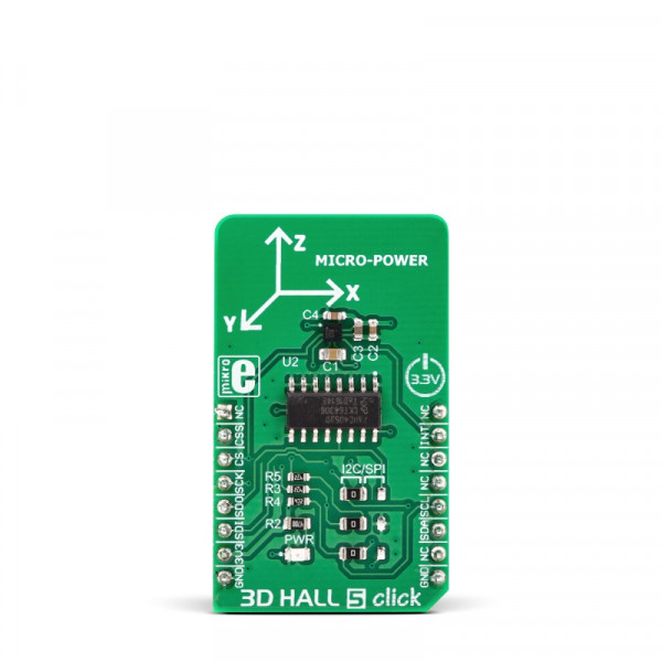
3D HALL 5 click


Prices incl. GST
Out of Stock.
- Product Code: MIKROE-3197
- MPN: MIKROE-3197
The features such as the embedded self-test, support for the hard iron compensation, selectable power mode, 16-bit data output, a wide dynamic range of the measurement (±50 gauss), all make this sensor a perfect choice for various IoT applications. The internal non-volatile memory contains the calibration parameters, making the Click board™ a very accurate spatial magnetic sensor, perfectly suited for the development of various position sensing applications, contactless knobs, encoders, switches, and potentiometers, or some other type of magnetic field measuring application, based on an accurate spatial sensing.
How does it work?
3D HALL 5 click carries the IIS2MDCTR, a low power 3D magnetic sensor, from STMicroelectronics. This sensor relies on a Hall effect to accurately sense magnetic field changes on three perpendicular axes. The internal magnetic field sensing elements are multiplexed and connected to a 16bit low noise Analog to Digital Converter (ADC), which sequentially samples each sensor, providing 16-bit spatial data over the digital interface. An additional thermal sensor is also available, and it is used for thermal compensation.
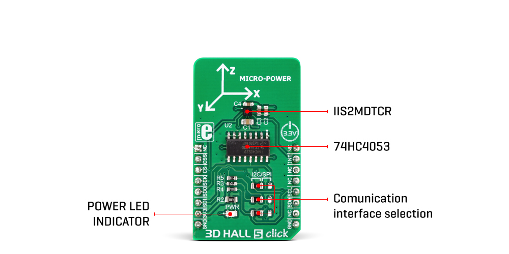
The magnetic sensor has a very low pin count. Therefore, SPI and I2C lines are multiplexed on the same pins. In addition, the SPI data in (SDI) and SPI data out (SDO) share the same pin. In order to allow functionality for both SPI read and SPI write functions, 3D HALL 5 click incorporates another IC: the 74HC4053, a triple 2-channel multiplexer/demultiplexer IC from NXP is used in conjunction with the RST pin of the mikroBUS™, labeled as CSS. This allows to demultiplex the SDI/SDO pin of the IIS2MDCTR and route the two resulting pins to appropriate pins of the mikroBUS™ (SDI and SDO).
The rest of the communication interface selection procedure relies on switching the appropriate SMD jumpers, grouped under the I2C/SPI label. Note that all of the I2C/SPI group jumpers need to be switched at the same side: all three should either be soldered as I2C or SPI. If one of them shows in the opposite position from the rest, the communication with the IC might not be possible.
The power consumption is a big concern as of lately, with the introduction of the IoT. The ability to work in a low power mode is a must for every device which is to be used for any type of IoT networking. The IIS2MDCTR magnetic sensor features two operational modes, with the addition of a low-pass filter (LPF). The power consumption is in a close relationship with the data output refresh rate (ODR). When operated in Low Power mode, and with the LPF and the offset cancelation turned OFF, the power consumption of the sensor alone drops down to 25 μA. Turning on the LPF and the offset cancelation will double the power consumption for the same ODR frequency to 50 μA, which is still in a domain of micropower consumption. However, filtering and offset cancelation options offer less noise and more accurate readings for both high-resolution and low-resolution modes.
The IIS2MDCTR magnetic sensor also features a powerful programmable interrupt engine, which allows many event sources to be signaled via the interrupt pin (INT/DRDY), which is routed from the sensor to the mikroBUS™ INT pin. A very useful function of the interrupt engine is the signaling of the data ready event. That way, the host MCU does not have to poll the sensor for the data acquisition. The sensor can simply trigger an interrupt when the data is ready for reading. The interrupt engine allows some other customizations of the interrupt signal, such as the polarity, pulse/latch mode, and so on.
The sensor provides raw data output, based on a strength of the magnetic field. The measurement is affected by many factors: slight manufacturing differences between ICs affect the readings, even the slight differences between Hall plates within the same IC might affect the accuracy, although the IC contains highly matched sensing elements. Also, the altitude might affect the readings, as well as temperature changes. Therefore, the sensor IC is equipped with the thermal sensor, used to measure the influence of the ambient temperature. Unlike errors which occur due to the influence of other parameters, the influence of the temperature is not linear, so a proper firmware development approach by using LUT tables is highly advisable.
The power mode, output data rate, interrupt thresholds for each axis, and other working parameters, including the availability of the I2C interface, are contained within the configuration registers of the IIS2MDCTR magnetic sensor. The sensor is highly configurable, with many configuration options. The IIS2MDCTR datasheet contains an in-depth explanation of all the registers and their functionality. However, 3D Hall 5 software library contains simplified functions that allow straight-forward readings to be performed, reducing the steps needed for a proper initialization and configuration of the device.
The Click board™ can operate with 3.3V MCUs only, it is set to work over the I2C by default, and it is already equipped with the pull-up resistors. It is ready to be used as soon as it is inserted into a mikroBUS™ socket of the development system.
Specifications
| Type | Hall effect,Magnetic |
| Applications | It is well-suited for development of various position sensing applications, contactless knobs, encoders, switches and potentiometers, or some other type of magnetic field measuring application, based on an accurate spatial sensing. |
| On-board modules | IIS2MDCTR, a low power 3D magnetic sensor, from STMicroelectronics; 74HC4053, a triple 2-channel multiplexer/demultiplexer IC from NXP |
| Key Features | The three independent Hall sensor channels allow high accuracy, additional thermal sensor for compensation. The small package case allows a very compact design while offering plenty of features, a programmable interrupt engine, low power consumption, and more |
| Interface | I2C,SPI |
| Input Voltage | 3.3V |
| Click board size | M (42.9 x 25.4 mm) |
Pinout diagram
This table shows how the pinout on 3D HALL 5 click corresponds to the pinout on the mikroBUS™ socket (the latter shown in the two middle columns).
| Notes | Pin | Pin | Notes | ||||
|---|---|---|---|---|---|---|---|
| NC | 1 | AN | PWM | 16 | NC | ||
| SDI/SDO Selection | CCS | 2 | RST | INT | 15 | INT | Interrupt |
| SPI Chip Select | CS | 3 | CS | RX | 14 | NC | |
| SPI Clock | SCK | 4 | SCK | TX | 13 | NC | |
| SPI SDO | SDO | 5 | MISO | SCL | 12 | SCL | I2C Clock/INT |
| SPI SDI | SDI | 6 | MOSI | SDA | 11 | SDA | I2C Data/ADDR |
| Power supply | +3.3V | 7 | 3.3V | 5V | 10 | NC | |
| Ground | GND | 8 | GND | GND | 9 | GND | Ground |
Onboard settings and indicators
| Label | Name | Default | Description |
|---|---|---|---|
| LD1 | PWR | - | Power LED indicator |
| JP1-JP3 | I2C/SPI | Left | Communication interface selection: left position I2C, right position SPI |
We provide a library for the 3D HALL 5 Click on our LibStock page, as well as a demo application (example), developed using MikroElektronika compilers. The demo can run on all the main MikroElektronika development boards.
Library Description
The library initializes and defines the I2C bus or SPI bus driver and drivers that offer a choice for writing data in register. The library includes function for read magnetics X/Y/Z axis data, set offset, read interrupt state and read temperature. The user also has the function for initializes chip.
Key functions:
int16_t c3dhall5_getAxis(uint8_t axis)- Functions for read axis data
uint8_t c3dhall5_init()- Functions for initialize the chip
void c3dhall5_writeByte(uint8_t reg, uint8_t _data)- Functions for write one byte in register
Example description
The application is composed of three sections :
- System Initialization - Initializes I2C/SPI module and sets CS pin and RST pin as OUTPUT and INT pin as INPUT
- Application Initialization - Initializes Driver init and chip init
- Application Task - (code snippet) - Reads the magnetics X / Y / Z axis data every 1 seconds.
void applicationTask()
{
axis_X = c3dhall5_getAxis(_C3DHALL5_AXIS_X);
mikrobus_logWrite(" X axis : ", _LOG_TEXT);
IntToStr(axis_X, demoText);
mikrobus_logWrite(demoText, _LOG_LINE);
axis_Y = c3dhall5_getAxis(_C3DHALL5_AXIS_Y);
mikrobus_logWrite(" Y axis : ", _LOG_TEXT);
IntToStr(axis_Y, demoText);
mikrobus_logWrite(demoText, _LOG_LINE);
axis_Z = c3dhall5_getAxis(_C3DHALL5_AXIS_Z);
mikrobus_logWrite(" Z axis : ", _LOG_TEXT);
IntToStr(axis_Z, demoText);
mikrobus_logWrite(demoText, _LOG_LINE);
mikrobus_logWrite("  ", _LOG_LINE);
Delay_ms( 1000 );
}
The full application code, and ready to use projects can be found on our LibStock page.
Other mikroE Libraries used in the example:
- I2C
- SPI
- UART
Additional notes and information
Depending on the development board you are using, you may need USB UART click, USB UART 2 click or RS232 click to connect to your PC, for development systems with no UART to USB interface available on the board. The terminal available in all MikroElektronika compilers, or any other terminal application of your choice, can be used to read the message.
mikroSDK
This click board is supported with mikroSDK - MikroElektronika Software Development Kit. To ensure proper operation of mikroSDK compliant click board demo applications, mikroSDK should be downloaded from the LibStock and installed for the compiler you are using.