
IR Grid click


Prices incl. GST
Out of Stock.
- Product Code: MIKROE-2622
- MPN: MIKROE-2622
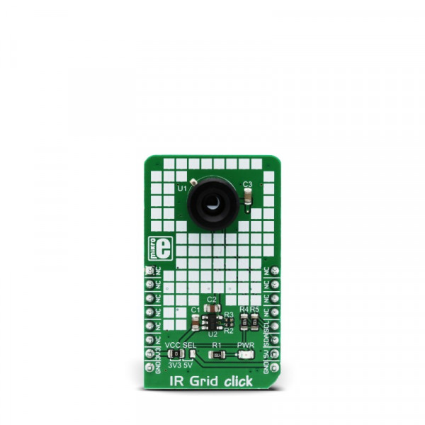
IR Grid click is a thermal imaging sensor. It has an array of 64 very sensitive factory calibrated IR elements (pixels), arranged in 4 rows of 16 pixels, each measuring an object temperature up to 300?C within its local Field of View (FOV). The MLX90621 IR sensor used on this Click board™ has only four pins, and it is mounted inside of the industry standard TO39 package. It is equipped with 2Kbit of EEPROM for storing the compensation and calibration parameters. The MLX90621BAD IR sensor array IC has I2C compatible digital interface, allowing it to be interfaced with a wide range of different MCUs. The sensor used on this Click board™ offers 40? x 10? FOV. The sensor can output up to 512 frames per second (FPS).
Due to the small number of external components it requires, as well as the low pin count and widely used I2C digital interface, this sensor is an ideal solution for building a range of thermal detection applications. IR Grid click can be used for a wide range of applications, including thermal scanners, precise contactless thermal measurement, thermal leaks in homes, industrial temperature control of moving parts, other types of heated object localization, human presence, and similar applications that require accurate contactless thermal measurement, or thermal imaging.
How does it work?
IR Grid click is equipped with the MLX90621BAD, a 16x4 IR array sensor, from Melexis. This sensor consists of two separate ICs in TO39 package: one IC is the sensor itself, labeled as MLX90670, while the second IC is the 2Kbit EEPROM labeled as 24AA02, used to store all the compensation and calibration parameters. These sensors can measure temperature relative to the cold junction temperature, and for this reason, the MLX90621 IR sensor incorporates a PTAT (Proportional to Absolute Temperature) compensation sensor. The IR sensor array, as well as the PTAT sensor readings, are sampled by fast internal ADC and stored on the RAM, which can be accessed via the I2C. The resolution of the ADC can be programmed between 15bit and 18bit. The sensor IC supports the I2C FM+ mode with transfer rate up to 1000 kbps, while the EEPROM IC supports up to Fast Rate (400 kbps).
The MLX90621BAD IR sensor used on this Click board™ offers 40? x 10? FOV, with the IR sensing elements arranged in a 4x16 grid. Each sensor measures the temperature in its individual FOV, allowing the host MCU to build a thermal image or calculate the temperature at each spot of the imaged scene. The measurement results are stored in the onboard RAM. 64 words, each 16 bits wide contains the result of the IR sensor measurements, and one word contains the PTAT measurement.
The configuration register allows configuring of the measurement parameters. This 16bit register contains bits that control the behavior of the sensor IC: the refresh rate, ADC resolution, measurement mode (continuous or step mode), sleep mode, I2C mode (FM or FM+), EEPROM disable/enable, etc. It also contains some flags, such as the POR/BOR (Power ON Reset/Brown Out Reset) indicator bit, and measurement in progress bit. For example, if the POR/BOR bit is set to 0, the initialization has to be repeated, as the calibration might not be valid any longer.
The EEPROM IC contains all the necessary calibration parameters, as well as the content of the configuration register, that may be used between the POR cycles. The manufacturer advises storing of the EEPROM content in the RAM of the MCU before measurement, especially if faster refresh rates are used. A certain workflow has to be followed when operating this sensor. The workflow includes calculation of the compensation parameters that are stored in the EEPROM for each element. Those calculations include ambient temperature calculation, pixel offset calculation, pixel to pixel sensitivity difference compensation, object emissivity compensation, and object temperature calculation. The datasheet of the MLX90621BAD IR sensor contains these equations, which use the parameters stored in EEPROM. However, this Click board™ is supported by the library, which contains functions that simplify working with this sensor.
It should be noted that the sensor measures the IR emissivity of an object, so it is to expect that some materials cannot be accurately measured by this sensor due to their low emissivity, such as the aluminum. To better understand the emissivity property of the materials, a person wearing clothes, can be taken as an example: the measured temperature will reflect the clothes temperature, rather than the body temperature itself, which is known to be about 37 ?C Care should be taken not to expose the Click board™ to a cold or hot air flow, as it will cause false readings of the real temperature. This sensor requires the temperature across the sensor package to be constant.
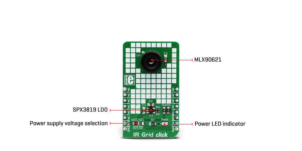
The MLX90621BAD IR sensor uses 2.6V for optimal results. To provide 2.6V, this Click board™ is equipped with the SPX3819, a small low noise LDO, which converts either 3.3V or 5V from the mikroBUS™ to the required 2.6V. The input voltage is selected by the SMD jumper labeled as VCC SEL. This jumper also selects the voltage at which I2C lines are pulled up, allowing both 3.3V and 5V MCUs to be interfaced with the Click board™. Besides I2C bus lines, no additional lines of the mikroBUS™ are used. I2C bus lines are routed to the respective pins of the mikroBUS™.
Specifications
| Type | Optical |
| Applications | It can be used for thermal scanners, precise contactless thermal measurement, thermal leaks in homes, industrial temperature control of moving parts, other types of heated object localization, human presence, and other similar applications. |
| On-board modules | MLX90621, a 16x4 IR array sensor with EEPROM, from Melexis |
| Key Features | 64 factory calibrated sensors, capable of contactless measuring of temperature up to 300?C, integrated 2048Kbit of EEPROM for storing configuration and compensation parameters, programmable refresh rate up to 512Hz, etc. |
| Interface | I2C |
| Input Voltage | 3.3V or 5V |
| Click board size | L (57.15 x 25.4 mm) |
Pinout diagram
This table shows how the pinout on IR Grid click corresponds to the pinout on the mikroBUS™ socket (the latter shown in the two middle columns).
| Notes | Pin | Pin | Notes | ||||
|---|---|---|---|---|---|---|---|
| NC | 1 | AN | PWM | 16 | NC | ||
| NC | 2 | RST | INT | 15 | NC | ||
| NC | 3 | CS | RX | 14 | NC | ||
| NC | 4 | SCK | TX | 13 | NC | ||
| NC | 5 | MISO | SCL | 12 | SCL | I2C Clock | |
| NC | 6 | MOSI | SDA | 11 | SDA | I2C Data | |
| Power supply | 3.3V | 7 | 3.3V | 5V | 10 | 5V | Power supply |
| Ground | GND | 8 | GND | GND | 9 | GND | Ground |
Onboard settings and indicators
| Label | Name | Default | Description |
|---|---|---|---|
| LD1 | PWR | - | Power LED indicator |
| VCC SEL | VCC SEL | Left | Power supply voltage selection: left position 3.3V, right position 5V |
Software support
We provide a demo application for IR Grid click on our Libstock page, as well as a demo application (example), developed using MikroElektronika compilers. The demo can run on all the main MikroElektronika development boards.
Library Description
Library performs IR and temperature measurement. The sensor gets an IR picture of the detected object (body) and measures ambient temperature, compares that two measurements and shows the IR picture as a 16x4 matrix. For more details check the documentation.
Key functions:
float irgrid_getTemperature(uint16_t ptat_data, uint16_t config_reg)- Returns value of ambient temperature.void irgrid_getIRArray(uint16_t *pixel_data)- Functions for reading IR pixels.void irgrid_measurement(uint8_t *Temperature)- Functions for reading all pixels temperature.
Example description
The application is composed of three sections:
- System Initialization - Initializes I2C module.
- Application Initialization - Initializes driver and IR Grid click.
- Application Task - (code snippet) - Reads pixels of temperature and creates temperature matrix which logs on USB-UART every 3 sec.
void applicationTask()
{
irgrid_measurement(Temperature);
mikrobus_logWrite("IR Grid Temperature matrix",_LOG_LINE);
for (irgrid_cnt = 0; irgrid_cnt < 64; irgrid_cnt++)
{
if(irgrid_cnt % 16 == 0)
{
mikrobus_logWrite(" ",_LOG_LINE);
}
if(Temperature[ irgrid_cnt ] < 36)
{
mikrobus_logWrite("/",_LOG_BYTE);
}
else
{
mikrobus_logWrite("*",_LOG_BYTE);
}
Delay_10ms();
}
mikrobus_logWrite(" ",_LOG_LINE);
Delay_ms(3000);
}
The full application code, and ready to use projects can be found on our Libstock page.
Other MikroElektronika libraries used in the example:
- I2C
- UART
Additional notes and information
Depending on the development board you are using, you may need USB UART click, USB UART 2 click or RS232 click to connect to your PC, for development systems with no UART to USB interface available on the board. The terminal available in all MikroElektronika compilers, or any other terminal application of your choice, can be used to read the message.
mikroSDK
This click board is supported with mikroSDK - MikroElektronika Software Development Kit. To ensure proper operation of mikroSDK compliant click board demo applications, mikroSDK should be downloaded from the LibStock and installed for the compiler you are using.