
WiFly click


Prices incl. GST
Out of Stock.
- Product Code: MIKROE-1937
- MPN: MIKROE-1937
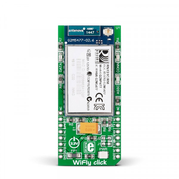
WiFly click carries RN-131, a standalone, embedded wireless LAN module. It allows you to connect your devices to 802.11 b/g wireless networks. Preloaded firmware simplifies integration. The mikroBUS UART interface alone (RX, TX pins) is sufficient to establish a wireless data connection (with speeds up to 1 Mbps); the module is controlled with simple ASCII commands (for scanning, authenticating and connecting to Wi-Fi networks). Multitude of networking applications are built in: DHCP, UDP, DNS, ARP, ICMP, TCP, HTTP client, and FTP client. Additional functionality is provided by RST, WAKE, RTSb and CTSb pins. 3.3V power supply only.
Specification
| Type | Wi-Fi |
| Applications | Easily connect to wireless networks for IoT, telemetry, remote equipment monitoring, data logging |
| On-board modules | RN-131 embedded wireless LAN module |
| Key Features | Qualified 2.4-GHz IEEE 802.11 b/g transceiver. Onboard ceramic chip antenna and connector for external antenna |
| Key Benefits | Preloaded firmware simplifies integration. Controlled through ASCII commands |
| Interface | GPIO,UART |
| Input Voltage | 3.3V |
| Compatibility | mikroBUS |
| Click board size | L (57.15 x 25.4 mm) |
WiFly click is the quickest way to add WiFi to your devices. The click features the well-known RN131 802.11 b/g Wi-Fi module from Microchip. With preloaded firmware and built in networking stacks, the integration of the WiFly click is really easy. RN131 is controlled with simple ASCII commands (for scanning, authenticating and connecting to Wi-Fi networks).
The click communicates with the MCU over UART connection and runs on a 3.3V power supply. It has an onboard ceramic chip antenna and a connector for an external antenna.
The RX, TX (UART) pins alone are enough for making a wireless data connection with speed up to 1 Mbps.
Features and usage notes
Low power consumption and speed
RN131 is a fully qualified and Wi-Fi certified 2.4 GHz IEEE 802.11 b/g transceiver. It is so power efficient it can run on two standard AAA batteries for years, considering it uses 40 mA (Rx) and 210 mA (Tx) when awake and 4 uA when it is in sleep mode. When it comes to speed, RN131 can wake up, connect to a wireless network, send data, and return to sleep mode in less than 100 milliseconds.
WiFi Protected Setup (WPS)
WiFi Protected Setup (WPS) protocol is designed for easy and secure establishment of wireless home networks. This protocol is meant to allow users who know little about wireless security to configure their WiFi Protected Access (WPA) without any trouble.
Networking applications
RN131 has built-in TCP/IP stack and networking applications, DHCP client, DNS client, ARP, ICMP ping, FTP client, Telnet, HTTP, UDP, and TCP. This makes it ideal for connecting IoT devices to wireless networks, for home automation systems, handheld devices, etc.
Onboard LEDs
- ASSOC (Red LED) —indicates the TCP/IP connection status. This signal is on high for an active connection, toggles fast to indicate no IP address, and toggles slowly to indicate that the IP address is OK but not connected.
- CONN (Green LED) — toggles when data is transferred.
- DATA (Yellow LED) — indicates the association status. High means the module is not associated with a network, off indicates that it is associated and Internet access is OK.
Pinout diagram
This table shows how the pinout on WiFly click corresponds to the pinout on the mikroBUS™ socket (the latter shown in the two middle columns).
| Notes | Pin | mikroBUStm | Pin | Notes | |||
|---|---|---|---|---|---|---|---|
| NC | 1 | AN | PWM | 16 | AP | Soft AP mode and factory reset. | |
| Module reset, Active Low | RST | 2 | RST | INT | 15 | NC | |
| Force the module to wakeup | WAKE | 3 | CS | TX | 14 | UART-TX | UART data Transmit |
| NC | 4 | SCK | RX | 13 | UART-RX | UART data Receive | |
| NC | 5 | MISO | SCL | 12 | RTSb | UART Request To Send | |
| NC | 6 | MOSI | SDA | 11 | CTSb | UART Clear To Send | |
| +3.3V power input | +3.3V | 7 | +3.3V | +5V | 10 | NC | |
| Ground | GND | 8 | GND | GND | 9 | GND | Ground |
Programming
This is a simple project which demonstrates the use of WiFly click board. After establishing the connection with the TCP server, messages from the server will be displayed on the TFT.
- NOTES:
- Place WiFly click board in the mikroBUS socket 1 on the EasyPIC Fusion v7 board.
- Configure SSID, TCP server address and port to match your network settings.
  1 #include "WiFly_Rn_131.h"
2 #include "resources.h"
3
4 // WiFly click connections
5 sbit WiFly_Rn_131_RST     at  LATC.B1;
6 sbit WiFly_Rn_131_RST_DIR at  TRISC.B1;
7 // WiFly click connections
8
9 unsigned char isConnect    = 0;
10 unsigned char isOpen       = 0;
11
12 unsigned char recMessage[2048];
13 unsigned char tmp;
14 unsigned int data_len = 0;
15 unsigned char data_ready    = 0;
16 unsigned char tryToConnect  = 0;
17 unsigned char recFromServer = 0;
18 unsigned char recMessServer = 0;
19
20 // Network/server information
21 char SSID_string[] ="mikroe_test";
22 char TCP_Server_port[] ="8001";
23 char TCP_Server_Address[] ="192.168.1.2";
24
25 void UART2interrupt() iv IVT_UART_2 ilevel 6 ics ICS_AUTO {
26   tmp = UART2_Read();
27
28   if (tmp == '>' || (tmp == 0x0D && recFromServer ) || data_len > 100) {
29     if(tmp == '>')
30       recMessage[data_len + 1] = '>';
31     else
32       recMessage[data_len + 1] = 0;
33     recMessage[data_len + 2] = 0;
34     data_ready = 1;
35   }
36   else {
37     if(recMessServer && (data_len == 5))
38       data_ready = 1;
39     recMessage[data_len] = tmp;
40     data_len++;
41   }
42   U2RXIF_bit = 0;
43 }
44
45 void resetUart(){
46   data_ready = 0;
47   data_len = 0;
48 }
49
50 void checkUartError(){
51   if(U2STAbits.OERR){
52     U2STAbits.OERR = 0;
53   }
54 }
55
56 void readData(){
57   while(!data_ready)
58     ;
59   resetUart();
60 }
61
62 void main() {
63   // Set all pins to digital
64   AD1PCFG = 0xFFFF;
65   JTAGEN_bit = 0;
66
67   // Set WiFly Reset pin as output
68   WiFly_Rn_131_RST_DIR = 0;
69
70   // Reset WiFly module
71   WiFly_Rn_131_RST = 1;
72   delay_ms(10);
73   WiFly_Rn_131_RST = 0;
74   delay_ms(10);
75   WiFly_Rn_131_RST = 1;
76   delay_ms(10);
77
78   DrawScreen();
79
80   // Initialize UART
81   UART2_Init(9600);
82
83   // Set UART interrupt
84   U2IP0_bit = 0;                     // Set UART2 interrupt
85   U2IP1_bit = 1;                     // Set interrupt priorities
86   U2IP2_bit = 1;                     // Set UART2 interrupt to level 6
87
88   U2RXIF_bit = 0;                    // Ensure interrupt not pending
89   U2RXIE_bit = 1;                    // Enable intterupt
90   EnableInterrupts();
91
92   // Enter command mode
93   WiFly_Rn_131_EnterInCmdMode();
94   delay_ms(100);
95
96   // Scan for the network
97   TFT_Write_Text("Scanning for the network...", 80, 60);
98   WiFly_Rn_131_Scan();
99   delay_ms(5000);
100
101   // Set network
102   WiFly_Rn_131_SetWlan(ssid_string);
103   delay_ms(100);
104
105   // Join network
106   TFT_Write_Text("Connecting to network...", 80, 80);
107   WiFly_Rn_131_JoinNet();
108   delay_ms(1000);
109
110   TFT_Write_Text("Connected to network!", 80, 100);
111
112   // Try to connect to TCP server
113   while(!isOpen) {
114     delay_ms(1000);
115     TFT_Write_Text("Connecting to TCP server...", 80, 125);
116     checkUartError();
117     resetUart();
118
119     // Connect to TCP server
120     WiFly_Rn_131_OpenConn("192.168.1.2", "8001");
121     readData();
122
123     recMessServer = 1;
124
125     while(!data_ready)
126       ;
127
128     if(strstr(recMessage, "OPEN")) {
129       isOpen = 1;
130       recMessServer = 0;
131     }
132     else {
133       tryToConnect++;
134       recMessServer = 0;
135     }
136
137     //  If not connected to TCP server
138     if(tryToConnect > 8) {
139       // Exit from command mode
140       WiFly_Rn_131_ExitFromCmdMode();
141       TFT_Write_Text("Can't connect to TCP server!", 80, 145);
142       while(1)
143         ;
144     }
145   }
146
147   TFT_Write_Text("Connected to TCP server!", 80, 145);
148   delay_ms(1000);
149   TFT_Write_Text("Received data :", 80, 170);
150
151   // Exit from command mode
152   WiFly_Rn_131_ExitFromCmdMode();
153
154   while(!data_ready)
155     ;
156
157   resetUart();
158   recFromServer = 1;
159
160   // Receive data from TCP server
161   while(1){
162     checkUartError();
163     while(!data_ready)
164       ;
165
166     TFT_Set_Pen(CL_WHITE, 10);
167     TFT_Set_Brush(1, CL_WHITE, 0, 0, 0, 0);
168     TFT_Rectangle(80, 190, 250, 205);
169     TFT_Write_Text(recMessage, 80, 190);
170
171     resetUart();
172   }
173 }