Prices incl. GST
Out of Stock.
- Product Code: MIKROE-1913
- MPN: MIKROE-1913
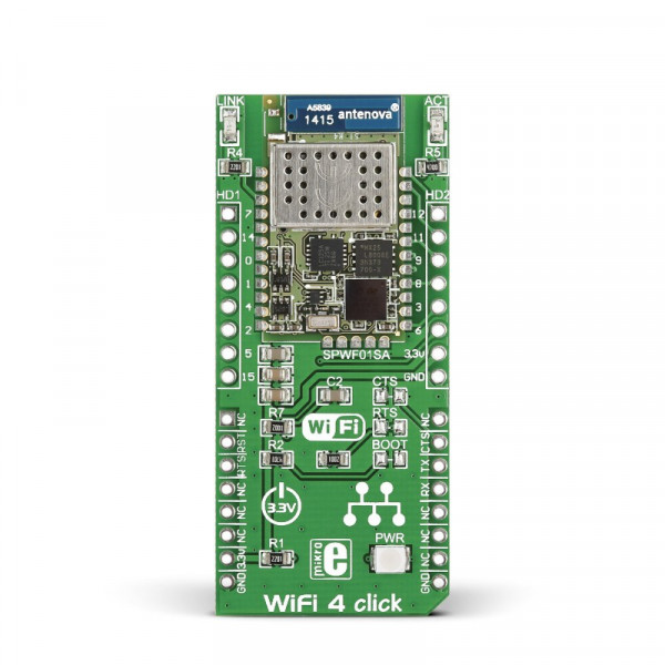
WiFi 4 click carries SPWF01SA, a complete standalone WiFi module with a single-chip 802.11 b/g/n transceiver, a 32-bit STM32 MCU, along with a built-in 2.4 GHz ISM band antenna.
The click is designed to run on a 3.3V power supply. It communicates with the target MCU over an UART interface (with additional functionality provided by Reset and Ready To Send pins, in place of default mikroBUS™ RST and CS pins).
SPWF01SA module
The SPWF01SA module has 1.5 MB of internal flash and 64 KB of RAM, and can achieve up to +18 dBm of output power.
In standby mode the module uses only 34 uA, while in sleep mode the typical power consumption is 15 mA.
Additional GPIO pins
The 14 additional GPIO pins that line the edges of the board have alternate functions like SPI, ADC, I2C, DAC (although access to those functions depends on the firmware version loaded in the module).
Key features
- SPWF01SA module
- 1.5 MB of internal flash memory
- 64 KB of RAM memory
- Integrated TCP/IP protocol stack
- WEP/WPA/WPA2 personal security
- Additional 14 GPIO pins
- Interface: UART
- 3.3V power supply
Specification
| Type | Wi-Fi |
| Applications | Connect things to the internet, create smart appliances, home automation systems, wireless data loggers and so on |
| On-board modules | SPWF01SA single-chip 802.11 b/g/n transceiver, a 32-bit STM32 MCU, along with a built-in 2.4 GHz ISM band antenna |
| Key Features | Fully integrated TCP/IP protocol stack. 64KB of RAM and 512 KB of Flash |
| Key Benefits | Additional GPIO pins, Additional Ready to Send and Reset pins |
| Interface | GPIO,UART |
| Input Voltage | 3.3V |
| Compatibility | mikroBUS |
| Click board size | L (57.15 x 25.4 mm) |
Pinout diagram
This table shows how the pinout on WiFi 4 click corresponds to the pinout on the mikroBUS™ socket (the latter shown in the two middle columns).
Programming
This code snippet is a demonstration on how to connect to wireless network router and start a simple web server.
It is necessary that your WIFi router has the DHCP turned on.
01 	   void main()
02 {
03     // initialize uart, timer, WiFi, TFT
04     initMCU();
05
06     // connect to the network
07     netReady = 0;
08     TFT_Write_Text( "Connecting to network...", 80 , 120 );
09
10     // Connect to network
11     if(( wifiTest = Net_Wireless_SPWF01S_ConnectToAP( "SSID", "password", 0 )) == _NET_WIRELESS_SPWF01S_OK )
12     {
13         // wait for WiFi to be up
14         while( netReady == 0 )
15             ;
16
17         TFT_Write_Text( "Connected!", 80 , 140 );
18
19         // Create webpage
20         Net_Wireless_SPWF01S_MakeFile( "index.html", html );
21         Net_Wireless_SPWF01S_MakeFile( "layout.css", layout );
22         Net_Wireless_SPWF01S_MakeFile( "logic.js", js );
23
24         // Get IP address
25         Net_Wireless_SPWF01S_GetCurrentIP( ipAddr );
26
27         // Convert IP address to string
28         ConvertIPtoString();
29
30         // Display IP address
31         TFT_Write_Text( "The IP address is :", 80 , 170 );
32         TFT_Write_Text( IPAdrStr, 195 , 170 );
33 } 


