
GSM3 click


Prices incl. GST
Out of Stock.
- Product Code: MIKROE-1720
- MPN: MIKROE-1720
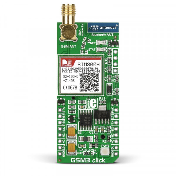
With GSM3 click you can have two of the most used wireless communication protocols in one device — GSM/GPRS and Bluetooth. The click has an onboard 2.4 GHz active antenna, so it is Bluetooth compatible. It carries the SIM800H quad-band GPS/GPRS module from SIMCOM.
GSM3 click is designed to use either 3.3V or 5V power supply and communicates with the target MCU over UART and the following mikroBUS pins: PWM, INT, AN, RST, CS.
Onboard antennas
The click has an SMA antenna connector and an audio input/output pad for connecting a microphone and earphones (which can also be used as an FM antenna).
Quad-band module
SIM800H has world-wide coverage — quad-band frequency: GSM 850, EGSM 900, DCS 1800 and PCS 1900. The module can search four frequency bands automatically.
Low power consumption
Typical power consumption in sleep mode is only 0.7mA. While in sleep mode the SIM800H can still receive SMS.
Key features
- SIM800H module
- GPRS data downlink/uplink transfer max: 85.6 kbps
- Supports GPRS coding schemes CS-1, CS-2, CS-3 and CS-4
- Integrated TCP/IP protocol stack
- Supports SIM card: 1.8V, 3V
- Bluetooth antenna pad
- Connection pad for audio input/output
- Interface: UART
- 3.3V or 5V power supply
Specification
| Type | GSM |
| Applications | GSM is a robust and reliable solution for communicating with your devices. Turn appliances on/off, exchange SMS messages for status updates and so on |
| On-board modules | SIM800H |
| Key Features | 2.4 GHz Bluetooth antenna, GSM antenna connector. SIM card socket integrated at the bottom side of the board |
| Key Benefits | Connection pad for audio input output |
| Interface | GPIO,UART |
| Input Voltage | 3.3V or 5V |
| Compatibility | mikroBUS |
| Click board size | L (57.15 x 25.4 mm) |
Pinout diagram
This table shows how the pinout on GSM3 click corresponds to the pinout on the mikroBUS™ socket (the latter shown in the two middle columns).
| Notes | Pin | mikroBUStm | Pin | Notes | |||
|---|---|---|---|---|---|---|---|
| Power on status | STAT | 1 | AN | PWM | 16 | PWRKEY | Power on/down of the module |
| Hardware reset of the module | RST | 2 | RST | INT | 15 | CTS | Request to send |
| Clear to send | RTS | 3 | CS | TX | 14 | TXD | Transmit data |
| Not connected | NC | 4 | SCK | RX | 13 | RXD | Receive data |
| Not coneected | NC | 5 | MISO | SCL | 12 | NC | Not connected |
| Not connected | NC | 6 | MOSI | SDA | 11 | NC | Not connected |
| Power supply | +3.3V | 7 | 3.3V | 5V | 10 | +5V | Power supply |
| Ground | GND | 8 | GND | GND | 9 | GND | Ground |
Programming
Code examples that demonstrate the usage of GSM3 click with MikroElektronika hardware, written for mikroC, mikroBasic and mikroPascal for PIC are available on Libstock.
Libstock also hosts an alternative extensive GSM library for a variety of hardware setups and with a detailed user manual.
This code snippet shows the initialization routine for the GSM3 click, when used with AT parser.
 1 void GSM3_init( void )
2 {
3     engine_init( gsm_default_handler );
4     hal_gsm_pwr( 0 );
5     Delay_ms( 100 );
6     hal_gsm_pwr( 1 );
7     Delay_ms( 2000 );
8     hal_gsm_pwr( 0 );
9
10     while( !hal_gsm_stat() );
11     Delay_ms( 10000 );
12
13     at_cmd( "AT" );
14     at_cmd( "AT+CSCS="GSM"" );
15     at_cmd( "AT+CMGF=1" );
16 }