
MPU 9DOF Click


Prices incl. GST
Out of Stock.
- Product Code: MIKROE-1719
- MPN: MIKROE-1719
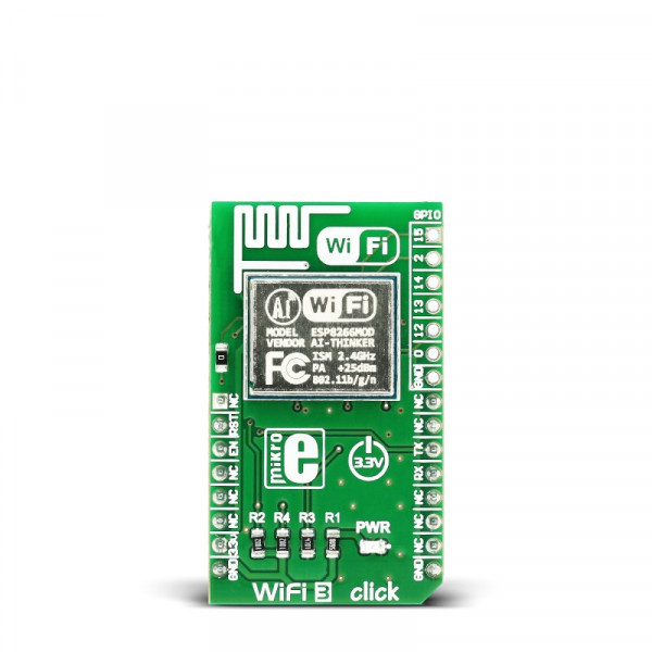
WiFi3 click is a complete self-contained WiFi solution carrying the ESP8266 module with a system on a chip. The click is designed to run on a 3.3V power supply only. It communicates with the target board microcontroller through the mikroBUS™ RX, TX, CS and RST lines.
ESP8266 WiFi module
The module supports standard IEEE802.11 b/g/n agreement and has an integrated TCP/IP protocol stack.
It also integrates antenna switches, an RF balun, power amplifier, low noise receive amplifier, power management modes and more.
The Standby power consumption of < 1.0mW is ideally suited for IoT projects and devices that need long battery life.
Ideally suited for IoT applications
WiFi3 click is ideally suited for IoT applications. The System on Chip offloads all the networking functions from the MCU. You can integrate it with sensors and actuators through its GPIOs and connect your things to the internet with minimum development effort.
PCB antenna
WiFi3 click features a PCB trace antenna, designed for the 2400–2483.5 MHz frequency band.
Specification
| Type | Wi-Fi |
| Applications | WiFi3 click makes it very simple to connect various “things” to the internet. Whether that “thing” is a simple LED, a data logger, or or any other type of sensor or switch in a smarthome |
| On-board modules | ESP8266 |
| Key Features | Integrated TCP/IP stack. PCB antenna |
| Key Benefits | Additional GPIO pins for connecting external electronics. Minimal software requirements for target board |
| Interface | UART,GPIO |
| Input Voltage | 3.3V |
| Compatibility | mikroBUS |
| Click board size | M (42.9 x 25.4 mm) |
Key features
-
PCB trace antenna
- ESP8266 WiFi module
- 802.11 b/g/n
- Integrated low power 32-bit MCU
- Integrated 10-bit ADC
- Integrated TCP/IP protocol stack
- Wi-Fi 2.4 GHz, support WPA/WPA2
- Interface: RX, TX, CS, RST
- 3.3V power supply
Pinout diagram
This table shows how the pinout on WiFi3 click corresponds to the pinout on the mikroBUS™ socket (the latter shown in the two middle columns).
| Notes | Pin | mikroBUStm | Pin | Notes | |||
|---|---|---|---|---|---|---|---|
| Not connected | NC | 1 | AN | PWM | 16 | NC | Not connected |
| Reset module | RST | 2 | RST | INT | 15 | NC | Not connected |
| Enable | EN | 3 | CS | TX | 14 | TX | UART Transmit |
| Not connected | NC | 4 | SCK | RX | 13 | RX | UART Receive |
| Not connected | NC | 5 | MISO | SCL | 12 | NC | Not connected |
| Not connected | NC | 6 | MOSI | SDA | 11 | NC | Not connected |
| Power supply | +3.3V | 7 | 3.3V | 5V | 10 | NC | Not connected |
| Ground | GND | 8 | GND | GND | 9 | GND | Ground |
Programming
Code examples for WiFi3 click, written for MikroElektronika hardware and compilers are available on Libstock.
Code snippet
The following code snippet shows the interrupt routine for receiving characters from the WiFi3 module.
01 void UART3_Interrupt() iv IVT_INT_USART3 ics ICS_AUTO
02 {
03     tmp = UART3_Read();
04     switch(tmp)
05     {
06     case LF:
07         if(data_len > 1)
08         {
09             data_ready = 1;
10         }
11         break;
12     case CR:
13         rx_buff[data_len] = 0;
14         break;
15     default:
16         rx_buff[data_len] = tmp;
17         data_len++;
18     }
19 } 