
BLE P click


Prices incl. GST
Out of Stock.
- Product Code: MIKROE-1597
- MPN: MIKROE-1597
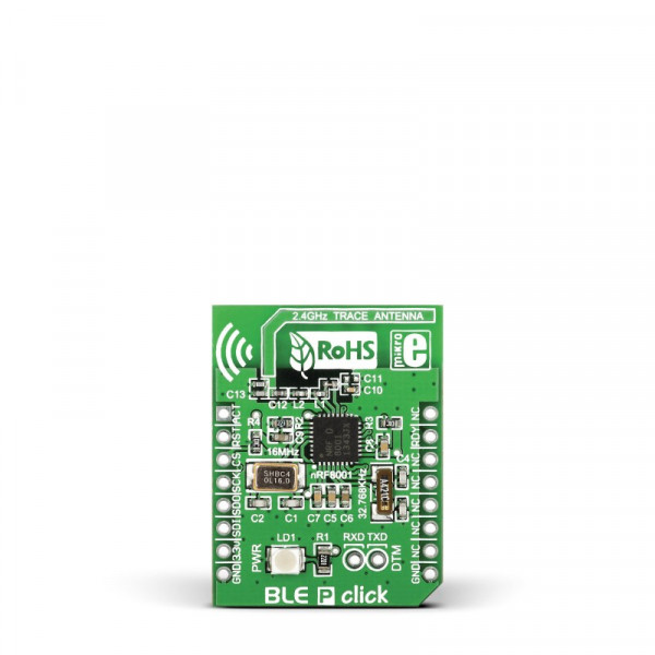
BLE P click carries the nRF8001 IC that allows you to add Bluetooth 4.0 to your device. The click communicates with the target board MCU through mikroBUS™ SPI (CS, SCK, MISO, MOSI), RDY and ACT lines, and runs on 3.3V power supply.
Beside the mikroBUS™ socket, BLE P click also features additional UART input and output pins (RXD and TXD). These enable you to test the RF parameters of the BLE P click’s radio design.
nRF8001
nRF8001 IC combines Radio, Link Layer and Host into a single product. The 16 MHz crystal oscillator is automatically enabled when nRF8001 requires it.
The built-in stack features a low energy PHY layer, LE link layer slave, LE host for devices in the peripheral role, and a Application Controller Interface.
PCB trace antenna
BLE P click features a PCB trace antenna, designed for the 2400-2483.5 MHz frequency band. Maximum device range is up to 40 meters in open space.
Low power consumption
The typical standby current consumption is only 2 mA. This kind of low power consumption is a great solution for today's smart devices, like fitness applications, medical devices, remotely controlling your home entertainment or home security systems, smart watches and many other things. It works by sending data when necessary and then powering down.
BLE or Bluetooth 4.0
BLE or Bluetooth 4.0 is Bluetooth Low Energy wireless network technology that allows users the same connection that the standard Bluetooth does but with much less power consumption.
BLE Android App
If you want to get started with BLE check out our BLE Android app that works on all devices with hardware and software support for BLE, just make sure you use it on Android devices.
Key features
- nRF8001 Bluetooth low energy RF transceiver
- 16 MHz crystal oscillator
- Ultra-low peak current consumption <14 mA
- Low current for connection oriented profiles, typically 2 μA
- PCB trace antenna
- BLE Android app
- Interface: SPI
- 3.3V power supply
Specification
| Type | BLE,Bluetooth |
| Applications | Developing smart devices requiring a Bluetooth Low Energy device in a peripheral role (sport and fitness gadgets, smart watches, proximity sensors...) |
| On-board modules | nRF8001 IC for adding a Bluetooth 4.0 |
| Key Features | Additional UART input and output pins (RXD and TXD) serve as a Direct Test Mode Interface |
| Key Benefits | Built-in stack features a low energy PHY layer, LE link layer slave, LE host for devices in the peripheral role, and a Application Controller Interface |
| Interface | GPIO,SPI |
| Input Voltage | 3.3V |
| Compatibility | mikroBUS |
| Click board size | S (28.6 x 25.4 mm) |
Pinout diagram
This table shows how the pinout on BLE P corresponds to the pinout on the mikroBUS™ socket (the latter shown in the two middle columns).
| Notes | Pin | mikroBUStm | Pin | Notes | |||
|---|---|---|---|---|---|---|---|
| Device RF front end activity indicator | ACT | 1 | AN | PWM | 16 | NC | Not connected |
| Reset (active low) | RST | 2 | RST | INT | 15 | RDY | ACI device ready indication |
| Chip select | CS | 3 | CS | RX | 14 | NC | Not connected |
| ACI clock input | SCK | 4 | SCK | TX | 13 | NC | Not connected |
| ACI Master In Slave Out | SDO | 5 | MISO | SCL | 12 | NC | Not connected |
| ACI Master Out Slave In | SDI | 6 | MOSI | SDA | 11 | NC | Not connected |
| Power supply | +3.3V | 7 | 3.3V | 5V | 10 | +5V | Power supply |
| Ground | GND | 8 | GND | GND | 9 | GND | Ground |
Programming
The code sets up the BLE P click, then continually parses Bluetooth low energy messages.
01: void main ()
02 {
03 UART1_Write_Text("Uart initialized");
04 UART1_Write(10);
05 UART1_Write(13);
06 GPIO_Digital_Output(&GPIOD_BASE, _GPIO_PINMASK_13);
07 GPIO_Digital_Input(&GPIOA_BASE, _GPIO_PINMASK_4);
08 GPIO_Digital_Input(&GPIOD_BASE, _GPIO_PINMASK_10);
09 GPIO_Digital_Output(&GPIOC_ODR, _GPIO_PINMASK_2);   // Set PC2 (RST) as digital output
10 GPIO_Digital_Output(&GPIOA_BASE, _GPIO_PINMASK_0);  // Set PA0 (CONN)
11
12
13 SPI3_Init_Advanced(_SPI_FPCLK_DIV128,
14                    _SPI_MASTER | _SPI_8_BIT | _SPI_CLK_IDLE_LOW |
15                    _SPI_FIRST_CLK_EDGE_TRANSITION | _SPI_LSB_FIRST | _SPI_SS_DISABLE |
16                    _SPI_SSM_ENABLE | _SPI_SSI_1,
17                    &_GPIO_MODULE_SPI3_PC10_11_12);
18
19 blep_hal_init();
20 // Do the BLE UART setup:
21 ble_uart_setup(MOSI_PIN, MISO_PIN, SCK_PIN, REQN_PIN, RDYN_PIN, RESET_PIN);
22
23 // Clear the serial buffer:
24 clear_serial_buffer();
25
26 while(1)
27 {
28     // Run the BLE UART loop once in every loop,
29     // to let it handle any BLE events
30     ble_uart_loop();
31
32     // handle all serial reads in one separate function:
33     handle_serial_input();
34 }
35
36 }