
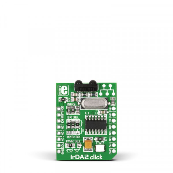
IrDA2 click


Prices incl. GST
Out of Stock.
- Product Code: MIKROE-1195
- MPN: MIKROE-1195
IrDA2 click is a compact and easy solution for adding infrared communication to your device. It features TFDU4101 infrared transceiver module as well as MCP2120 infrared encoder/decoder from Microchip connected with the 7.3728 MHz external crystal. The click is designed to run on either 3.3V or 5V power supply. It communicates with the target board via UART interface and the following mikroBUS™ pins: AN, RST, CS.
Essential features
The combination of the TFDU4101 and MCP2120 results in support for fast and stable infrared data communication. The TFDU4101 infrared transceiver module covers the full IrDA range of more than 1m and speed up to 115.2 kbit/s.
Application
With low power consumption, all these features make IrDA2 click ideal for TV and video systems, printers, fax machines, copiers, external infrared adapters, diagnostic systems and other industrial applications.
Key features
-
MCP2120 infrared encoder/decoder
- Up to IrDA standard 115.2 kbaud operation
- TFDU4101 infrared transceiver
- UART interface
- 3.3V or 5V power supply
Specification
| Type | Optical |
| Applications | IrDA2 board is ideal for wireless infra red data communication with PC remote controllers for home applicances and other devices. |
| On-board modules | MCP2120 infrared encoder/decoder, TFDU4101 infrared transceiver |
| Key Features | Data Communication rates up to 115.2kbaud. Interfaces with IrDA compliant transcievers with 1.63us Transmit/Receive format |
| Key Benefits | Low power consumption. Includes UART to IrDA standard bit encoder/decoder functionality |
| Interface | GPIO,UART |
| Input Voltage | 3.3V or 5V |
| Compatibility | mikroBUS |
| Click board size | S (28.6 x 25.4 mm) |
Pinout diagram
This table shows how the pinout on IrDA2 click corresponds to the pinout on the mikroBUS™ socket (the latter shown in the two middle columns).
| Notes | Pin | mikroBUStm | Pin | Notes | |||
|---|---|---|---|---|---|---|---|
| Selects the device mode (Data/Command) for Software Baud Rate operation | MODE | 1 | AN | PWM | 16 | NC | Not connected |
| Resets the device | RESET# | 2 | RST | INT | 15 | NC | Not connected |
| Device Enable | ENABLE | 3 | CS | TX | 14 | TX | UART Transmit |
| Not connected | NC | 4 | SCK | RX | 13 | RX | UART Receive |
| Not connected | NC | 5 | MISO | SCL | 12 | NC | Not connected |
| Not connected | NC | 6 | MOSI | SDA | 11 | NC | Not connected |
| Power supply | +3.3V | 7 | 3.3V | 5V | 10 | +5V | Power supply |
| Ground | GND | 8 | GND | GND | 9 | GND | Ground |
SMD jumpers
Jumpers J0, J1 and J2 connect MCP2120 controller BAUD0, BAUD1 and BAUD2 pins to VCC or GND. You can change baud rate settings by soldering J0, J1 and J2 in the appropriate position (Table 1). These jumpers are soldered in logic 1 position by default (9600 bps, software selection enabled). SMD jumper J3 is used to select 5V or 3.3V power supply (default position is 3.3V).
Table 1: Baud Rate selection
| B2 | B1 | B0 | Software selection | Hardware selection | Baud Rate (bps) |
|---|---|---|---|---|---|
| 0 | 0 | 0 | • | 9600 | |
| 0 | 0 | 1 | • | 19200 | |
| 0 | 1 | 0 | • | 38400 | |
| 0 | 1 | 1 | • | 57600 | |
| 1 | 0 | 0 | • | 115200 | |
| 1 | 1 | 1 | • | 9600 |
Programming
Code examples for IrDA2 click, written for MikroElektronika hardware and compilers are available on Libstock.
Code snippet 1 - MASTER
This example demonstrates the functionality of the IrDA2 Click board.
The master initiates communication with the slave by sending 1 byte of data to the slave.
01 void main() {
02   ANSELC = 0;                      // Configure ports as digital I/O
03   ANSELD = 0;
04   TRISD = 0;                       // Set PORTD as output
05
06   i = 0;                           // Initialize global variables
07   received = 0;
08
09   UART1_Init(9600);                // Initialize UART module at 9600 baud rate
10   delay_ms(200);
11
12   RC1IE_bit = 1;                   // Enable USART Receiver interrupt
13   GIE_bit = 1;                     // Enable Global interrupt
14   PEIE_bit = 1;                    // Enable Peripheral interrupt
15
16   UART1_Write(1);                  // Master initiates communication
17
18   while(1) {
19     if (received) {                // If data received by Slave
20       LATD = i;                    //   display it on the PORTD
21       i++;                         // Increment counter
22       received = 0;                // Clear received flag
23     }
24     UART1_Write(i);                // Send counter value to Slave via UART1
25     delay_ms(200);
26   }
27 }
Code snippet 2 - SLAVE
The slave accepts data, increments it and sends it back to the master.
The data received is shown on PORTD.
01 void main() {
02   ANSELC = 0;                      // Configure ports as digital I/O
03   ANSELD = 0;
04   TRISD = 0;                       // Set PORTD as output
05
06   i = 0;                           // Initialize global variables
07   received = 0;
08
09   UART1_Init(9600);                // Initialize UART module at 9600 baud rate
10   Delay_ms(200);
11
12   RC1IE_bit = 1;                   // Enable USART Receiver interrupt
13   GIE_bit = 1;                     // Enable Global interrupt
14   PEIE_bit = 1;                    // Enable Peripheral interrupt
15
16   while(1) {
17     if (received) {                // If data received,
18       LATD = i;                    //   display it on the PORTD
19       i++;                         // Increment counter
20       received = 0;                // Clear received flag
21       UART1_Write(i);              // Send counter value to Master via UART1
22     }
23   }
24 }